
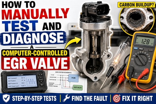
A check-engine light and an EGR trouble code do not automatically mean the EGR valve needs to be replaced. The code tells you that the engine computer detected something about EGR operation that did not happen as expected. The valve could be sticking, the position sensor could be reporting incorrectly, the wiring could have a problem, the computer may not be controlling the circuit properly, or carbon buildup could be restricting exhaust flow.
The purpose of diagnosis is to determine which of those problems is actually occurring before replacing parts.
A scan tool is extremely useful for this work, but it is not the only way to diagnose a computer-controlled EGR system. Bidirectional controls can time out, communication problems can interrupt testing, and less capable scan tools may not allow the EGR valve to be commanded at all. When that happens, understanding the electrical circuit allows many of the same tests to be performed manually with a multimeter, an appropriate automotive test light, fused jumper leads, and preferably a wiring diagram.
This lesson focuses on a common linear EGR design containing both an electrically operated valve and an EGR position sensor. The source vehicle used a five-wire linear EGR valve with two circuits controlling the solenoid and three circuits serving the position sensor. The exact connector arrangement, wire colors, voltages, switching strategy, and relearn procedure can vary considerably between vehicles, so the principles in this lesson should be combined with the correct service information for the vehicle being tested.
What the EGR System Actually Does
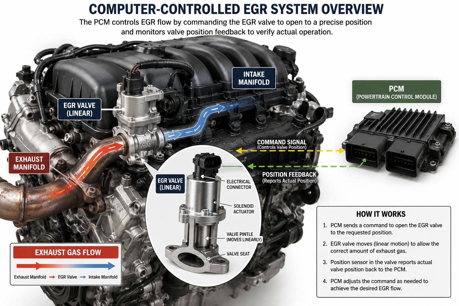
EGR stands for Exhaust Gas Recirculation. Under certain operating conditions, the engine management system allows a controlled amount of exhaust gas to enter the intake stream. Introducing this inert exhaust gas helps reduce peak combustion temperatures and therefore helps control nitrogen oxide emissions.
The PCM, or Powertrain Control Module, must know more than whether the EGR valve is simply on or off. On a linear EGR system, the computer can control how far the valve opens and monitor whether the valve actually reached the requested position.
That ability is extremely useful diagnostically.
If the PCM commands the valve to open but the position sensor says it barely moved, something is wrong. If the valve opens but does not return completely to its seat, something is wrong. If the valve moves normally but opening it produces almost no change in engine operation, the valve may be fine while the EGR passages are restricted.
The diagnostic goal is therefore to compare command, movement, feedback, and actual exhaust flow.
Understanding a Five-Wire Linear EGR Valve
Before touching a test light or jumper wire, understand what is inside the valve.
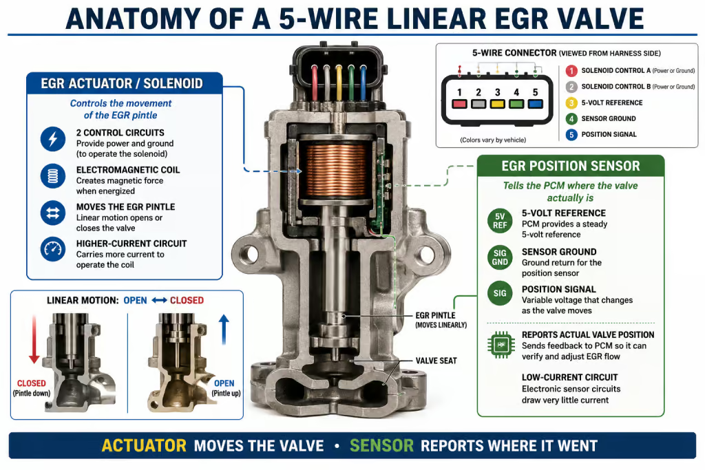
A common five-wire linear EGR assembly is essentially two electrical devices packaged together. One is an electromagnetic actuator or solenoid that moves the EGR pintle. The other is a position sensor that tells the PCM where the valve actually is.
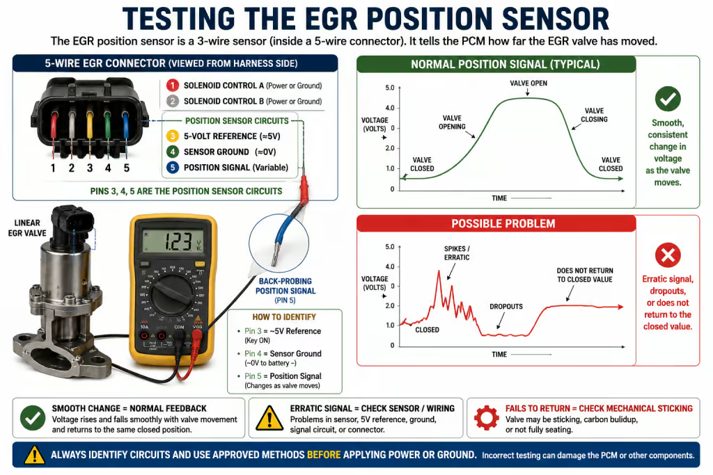
On the design demonstrated in the source material, the two outside terminals operated the solenoid while the three center circuits were associated with the position sensor.
The three position-sensor circuits typically consist of a 5-volt reference, sensor ground, and position signal.
The distinction between the actuator and sensor circuits is extremely important because they should not be treated the same way.
The position sensor is a low-current electronic circuit. A digital multimeter is normally the appropriate tool for examining its reference, ground, and signal circuits.
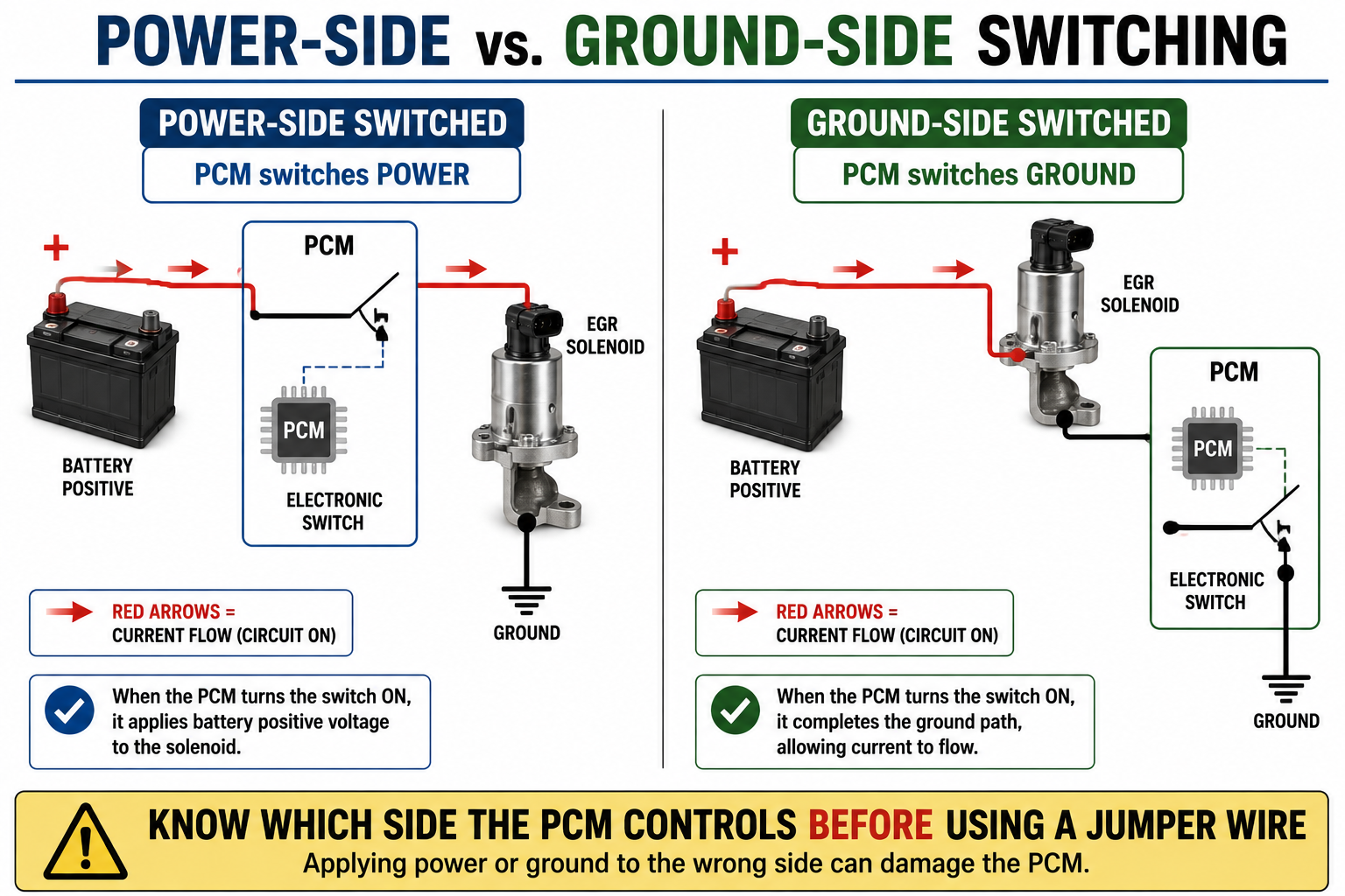
The solenoid is a higher-current actuator. Depending on the design, the PCM may operate it by switching voltage or by switching ground.
Understanding which circuit you are working on is one of the most important protections against accidentally damaging the engine computer.
Tools for the Job
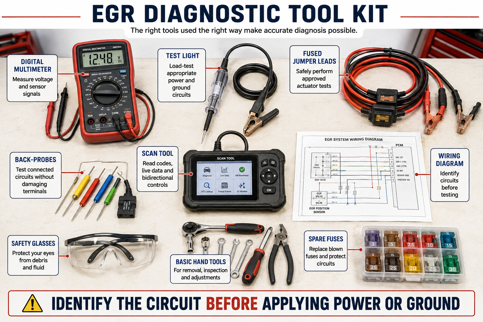
A thorough manual diagnosis can be performed with relatively basic automotive electrical equipment. A digital multimeter is essential. An appropriate automotive test light can be extremely useful for identifying certain powers and grounds under load. Proper back-probing pins help prevent connector damage, while fused jumper leads provide additional protection during manual actuator testing.
A vehicle-specific wiring diagram is strongly recommended.
A scan tool is useful even when it cannot command the EGR valve because live data may still show EGR command, actual EGR position, position-sensor voltage, learned closed position, and diagnostic trouble codes.
The objective is not to choose between a scan tool and manual tools. The strongest diagnosis often comes from using both.
Before Testing – Protect the PCM
Manual actuator testing can damage a control module if it is performed incorrectly.
Do not apply battery voltage or ground to an EGR control wire merely because the wire appears to be the correct one. Do not assume another vehicle with a similar connector uses the same wiring arrangement.
A PCM operates many actuators through electronic driver circuits. If battery positive or ground is applied to the wrong side of that circuit, the result can be a direct electrical conflict with the PCM driver.
That can destroy the driver inside the computer.
Whenever possible, obtain the correct wiring diagram first. Identify the actuator circuits, 5-volt reference, sensor ground, and position signal before applying external power.
If the circuit cannot be positively identified, disconnect the EGR valve from the vehicle wiring and perform component-level testing according to the manufacturer’s information rather than backfeeding the connected PCM circuit.
The original demonstration specifically warns that incorrect jumper-wire placement can damage the computer driver.
Manual testing should bypass limitations of the scan tool. It should never bypass electrical safety.
Step 1 – Retrieve and Record the Trouble Codes
Begin with the diagnostic trouble codes.
Do not immediately clear them.
Record stored, pending, and permanent codes when available. Also save freeze-frame information because it can reveal the operating conditions present when the fault occurred.
An EGR range or performance code does not necessarily identify the failed component. It simply tells you that the PCM observed EGR behavior outside the expected range.
For example, the PCM may have commanded the valve closed but continued receiving a signal indicating that the valve was partially open. Alternatively, it may have commanded the valve open without seeing the expected position change.
Those are very different failures even though both involve the EGR system.
The code is therefore the beginning of the diagnosis rather than the conclusion.
Step 2 – Inspect the System Before Electrical Testing
Perform a visual inspection before connecting jumper wires or meters.
Check the EGR connector for corrosion, broken locking tabs, loose terminals, damaged insulation, previous repairs, and wiring that may have contacted hot exhaust components.
Look for obvious vacuum or intake problems if the engine design uses additional EGR-related plumbing.
Inspect accessible EGR passages for obvious carbon accumulation.
Also consider whether other engine problems could affect EGR operation. Severe misfires, incorrect engine temperature information, throttle problems, or other engine-management faults can sometimes prevent normal EGR operation.
Correct major engine problems before interpreting unusual EGR behavior.
Step 3 -Examine EGR Live Data
Turn the ignition on and examine the available EGR data.
Look for parameters such as EGR command, desired EGR position, actual EGR position, EGR position voltage, and learned closed-position voltage.
The names will vary by manufacturer and scan tool.
Do not become fixated on one exact voltage number.
Instead, look at relationships.
When the valve is closed, the position signal should be reasonably consistent. When the valve opens, the signal should change. When the valve closes again, it should return close to the expected closed value.
In the source demonstration, the valve responded to a command but failed to return to its previous closed-position reading, immediately raising suspicion that the valve was sticking.
That is an important diagnostic clue.
Repeatability matters more than one isolated reading.
Step 4 – Perform a Bidirectional Test If Available
If the scan tool provides EGR output controls, command the valve through several positions.
Start low and increase the command gradually.
Watch actual EGR position or position-sensor voltage while changing commanded EGR.
The feedback should respond reasonably smoothly as the command increases. When the command returns to zero, the position should return consistently toward its closed value.
Do the test several times.
A valve that opens correctly once but sticks the next time is not functioning correctly.
If the scan tool times out, loses communication, or does not provide bidirectional controls, manual testing becomes particularly valuable.
Step 5 – Identify the EGR Solenoid Circuit
Before manually energizing anything, determine whether the EGR actuator is controlled on the power side or ground side.
This concept is fundamental to diagnosing computer-controlled actuators.
A circuit needs both power and ground for current to flow.
In a power-side switched circuit, the ground side is available and the computer controls when voltage is supplied.
In a ground-side switched circuit, power is available and the computer controls when the ground path is completed.
The source demonstration showed a useful diagnostic example. With the EGR circuit inactive, both actuator wires measured approximately zero volts. Further testing identified the system as power-side switched, with one side providing the ground path and the other receiving switched positive voltage.
That pattern was appropriate for that particular circuit.
Do not assume every EGR system works the same way.
The correct wiring diagram should always take priority.
Step 6 – Use a Test Light to Verify the Appropriate Ground Circuit
Once a potential ground circuit has been identified, an automotive test light can be useful because it places a small electrical load on the circuit.
For a suitable ground-circuit test, connect the test light appropriately to battery positive and carefully probe the suspected ground terminal according to the wiring diagram and testing procedure.
A bright test light indicates that the circuit can carry at least the current required by the light.
This is different from simply measuring voltage with a digital multimeter.
A digital meter has extremely high internal resistance and draws very little current. A badly corroded wire may sometimes produce a seemingly normal voltage measurement even though it cannot carry enough current to operate the component.
A test light introduces a load.
That makes it particularly useful for evaluating certain power and ground circuits.
In the source demonstration, the test light was used to distinguish the constant ground side from the switched positive side of the actuator circuit.
Do not force meter probes or test-light probes into connector terminals. Enlarging a terminal can create a new intermittent fault.
Step 7 – Identify the EGR Position-Sensor Circuits
Now move to the three-wire position sensor.
With the circuit connected and safely back-probed, identify the 5-volt reference, sensor ground, and position signal.
The reference should normally be close to 5 volts.
Sensor ground should normally be very close to zero volts.
The remaining circuit should be the position signal.
On the vehicle demonstrated in the source material, testing identified approximately 5 volts on the reference circuit, near-zero voltage on sensor ground, and a lower voltage on the signal circuit with the valve closed.
Those exact values are not universal specifications.
What matters is that the reference and ground are correct and that the signal changes appropriately when the valve moves.
Step 8 – Watch the Position Signal
Monitor the position-sensor signal with a digital multimeter or suitable diagnostic equipment.
The signal should change smoothly as the valve moves.
This test can reveal several different problems.
If the valve physically moves but the signal remains unchanged, there may be a position-sensor or signal-circuit problem.
If the signal suddenly drops out or jumps erratically while the valve moves smoothly, suspect an electrical problem within the sensor or its wiring.
If the signal rises normally as the valve opens but fails to return to the same closed value, mechanical sticking becomes more likely.
That distinction prevents unnecessary parts replacement.
Step 9 – STOP Before Using a Jumper Wire
This is the most important safety point in the procedure.
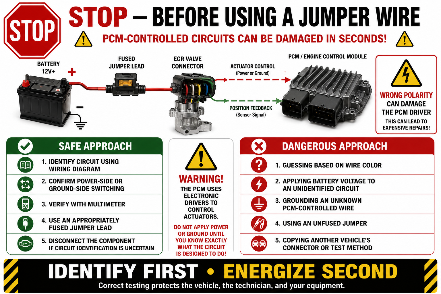
Do not connect battery positive or ground to an EGR control circuit until you know exactly what that circuit does.
Suppose the PCM is designed to supply battery voltage on one wire. If that wire is mistakenly grounded with a jumper while the PCM turns its driver on, the driver may effectively be switched directly into a short circuit.
The result can be a damaged PCM.
If you cannot positively determine the switching strategy, unplug the EGR valve and perform a component-level test using the correct terminal identification and appropriately fused jumper leads.
Do not guess.
Do not rely only on wire color.
Do not copy a jumper configuration from a different vehicle.
Identify first. Energize second.
Step 10 – Manually Energize the EGR Valve
Once the actuator circuits have been positively identified and the service information confirms that manual activation is appropriate, the solenoid can be briefly energized.
Use an appropriately fused jumper lead.
The valve should normally produce a noticeable movement or click when energized.
At the same time, monitor the EGR position signal.
You are looking for two things:
Did the valve move?
Did the sensor correctly report that movement?
In the source example, manual activation produced a substantial change in the position signal, proving that the valve could move and that the position sensor could detect that movement. However, after power was removed, the signal failed to return consistently to the expected closed position.
That was strong evidence of mechanical sticking.
Step 11 – Cycle the Valve Repeatedly
One successful movement does not prove that the valve is healthy.
Open and close it several times.
Watch the signal every time.
A healthy system should behave predictably. The valve should respond when energized and return consistently when power is removed.
A sticking valve may work perfectly during one cycle and hang during the next.
Watch for slow movement, inconsistent return position, delayed opening, partial movement, or a valve that occasionally requires vibration or movement before operating.
Intermittent sticking is especially important because it can create a trouble code even when the valve appears normal during a quick inspection.
Step 12 – Test Actual EGR Flow
At this point you may know that the valve moves electrically, but that still does not prove that exhaust gas can reach the intake.
The passages themselves can become restricted by carbon.
This is where an engine-running EGR test becomes useful.
With the engine idling and only after confirming that the valve can be safely commanded or energized according to the proper procedure, briefly open the EGR valve.
On many gasoline engines, substantial EGR flow at idle disrupts combustion because the engine is receiving exhaust gas at a time when it normally needs a relatively stable fresh-air mixture.
The engine should therefore run noticeably rough. With enough EGR flow, it may nearly stall or completely stall.
That reaction is useful information.
If the valve clearly opens and the engine immediately struggles or stalls, exhaust gas is reaching the cylinders. That strongly suggests the passages are capable of flowing.
In the source demonstration, opening the valve caused the engine to stall, helping confirm that the EGR flow path itself was functioning.
If the valve opens fully but engine idle barely changes, investigate restricted EGR passages.
Step 13 – Remove the Valve If Sticking Is Confirmed
Allow the engine and exhaust components to cool before removing the EGR valve.
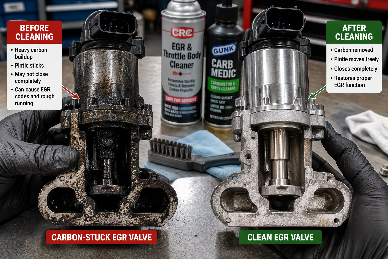
Once removed, inspect the pintle, valve seat, and accessible passages.
Carbon accumulation is common.
Carefully check whether the valve moves freely if its design permits manual movement.
A sticking pintle may hang partially open, resist opening, or fail to return completely to its seat.
That mechanical problem can explain why the position sensor appears electrically functional while the PCM still reports an EGR position error.
Step 14 – Clean the Valve When Appropriate
Not every contaminated EGR valve needs immediate replacement.
Some can be cleaned successfully.
Use only a cleaner suitable for the component and follow manufacturer guidance. Keep aggressive solvents away from electrical sections that are not designed for chemical exposure.
Remove carbon carefully from the pintle and seating area.
Do not reshape the valve seat, bend the pintle, force the mechanism, or aggressively grind components.
After cleaning, move the valve repeatedly if its design allows it.
The valve should move freely and return consistently.
If it still catches, sticks, binds, or returns unpredictably, replace it.
The source demonstration followed this same principle: the valve was cleaned and then repeatedly exercised to determine whether it could return consistently before being accepted for continued use.
Step 15 – Inspect the EGR Passages
With the valve removed, inspect accessible exhaust and intake passages for carbon buildup.
Do not assume the passages are open merely because the valve was dirty.
Heavy carbon deposits can dramatically reduce EGR flow.
If cleaning is necessary, prevent loosened carbon from falling into places where it could cause additional problems. Follow the manufacturer’s procedure for passage cleaning whenever available.
A system with a perfectly functioning valve can still set EGR flow codes when the passages are restricted.
Step 16 – Reinstall the Valve
Inspect the mounting surfaces and gasket.
Use a new gasket where required and install the valve according to manufacturer instructions.
Tighten the fasteners to the correct specification rather than guessing.
Reconnect the electrical connector and verify that its locking mechanism engages properly.
Before moving on, inspect the wiring one more time for heat damage, rubbing, contamination, or stretched sections.
Step 17 – Repeat the Manual Test
After installation, cycle the valve again if the test procedure allows it.
Monitor the position signal.
You are now looking for consistency.
The valve should open when commanded and return to approximately the same closed position every time.
Repeated return to the same position is often more meaningful than achieving one perfect voltage reading.
If the valve begins sticking again immediately after cleaning, replacement is usually the better repair.
Step 18 – Repeat the Scan-Tool Test
If bidirectional controls are available, return to the scan tool.
Command several EGR positions and compare command with actual position.
As commanded opening increases, actual position should respond appropriately.
Return the command to zero.
The valve should return toward its expected closed position.
Repeat the test several times.
A slight delay between command and actual movement can be normal, but large discrepancies, erratic changes, or inconsistent closed positions deserve further investigation.
Step 19 – Check the EGR Closed-Position Relearn
Some PCM strategies learn the normal closed position of the EGR valve.
Cleaning carbon from the seat or installing another valve may change the closed-position signal slightly.
That does not necessarily indicate a new fault.
Depending on the vehicle, the PCM may relearn the position automatically during startup, after one or more key cycles, through a scan-tool procedure, or through another manufacturer-specific process.
Do not automatically disconnect the battery.
In the source vehicle, further testing showed that the PCM could update its closed-position information during startup and operation rather than requiring the battery-disconnect procedure initially considered.
Always follow the relearn procedure specified for the particular vehicle.
Step 20 – Clear the Codes and Perform a Test Drive
After completing the repair, clear the appropriate trouble codes and start the engine.
Verify normal idle operation.
During the road test, monitor commanded and actual EGR position if possible.
The two values should follow each other reasonably closely when EGR operation occurs.
Pay particular attention to what happens when EGR command decreases.
A valve that opens properly but occasionally fails to close can still trigger another fault.
After the drive, scan the vehicle again.
Check stored, pending, and permanent codes and confirm that EGR-related data remains reasonable.
Do not consider the repair finished simply because the check-engine light went out.
Verify the repair.
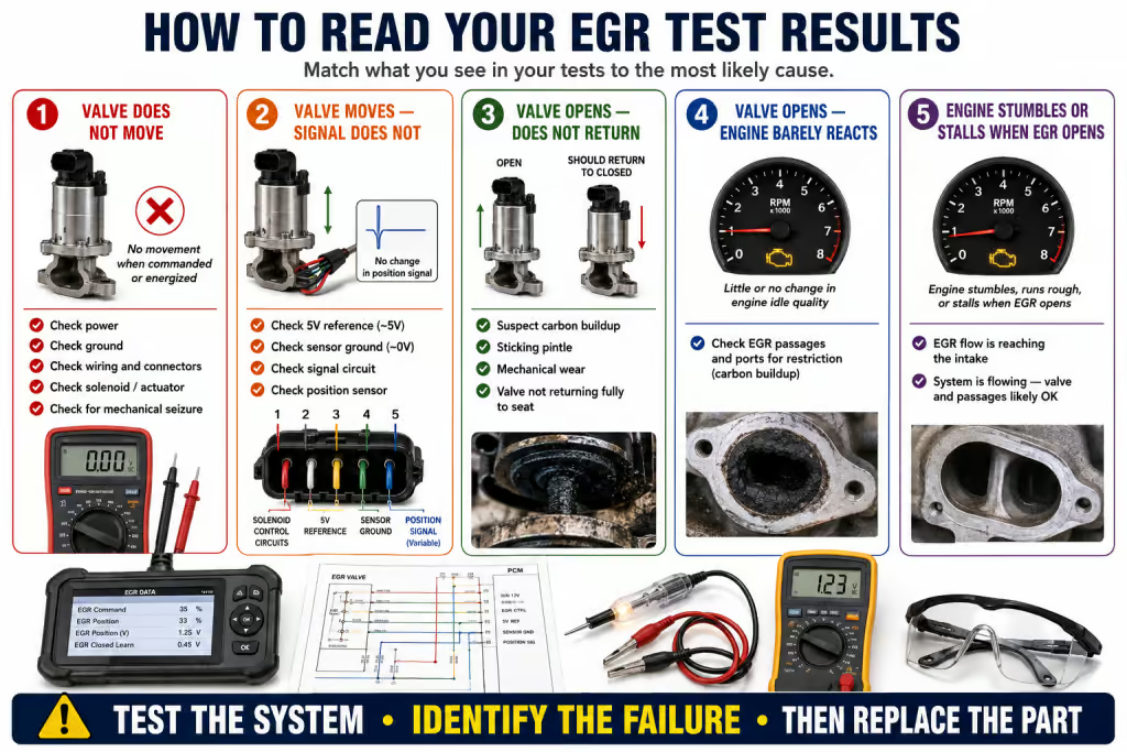
How to Read the Results
The real value of this procedure is that the results point toward different failures.
The EGR Valve Does Not Move When Correctly Energized
If proper power and ground are present but the valve does not move, suspect a failed solenoid, internal mechanical seizure, or failed EGR assembly.
The Valve Moves but Position Voltage Does Not Change
The actuator may be functioning while the feedback system is not.
Check the 5-volt reference, sensor ground, signal circuit, connector terminals, and internal position sensor.
Position Voltage Changes but Does Not Return Consistently
This is a strong clue for mechanical sticking.
Carbon buildup, a binding pintle, contamination, or internal mechanical wear may prevent the valve from returning completely to its seat.
The Valve Opens but the Engine Barely Reacts
If the valve is definitely opening but idle quality barely changes during an appropriate flow test, investigate restricted EGR passages.
The electrical system may be functioning perfectly while carbon prevents exhaust gas from reaching the intake.
The Engine Runs Extremely Rough or Stalls
If manually opening the EGR valve at idle produces an immediate major change in engine operation, significant EGR flow is reaching the intake.
That helps separate a valve-control problem from a blocked-passage problem.
Commanded and Actual EGR Do Not Agree
Do not immediately blame the valve.
Determine whether the disagreement originates from actuator movement, position feedback, circuit integrity, mechanical sticking, passage restriction, or learned-position calibration.
Each possibility can be tested.
A Simple Diagnostic Path
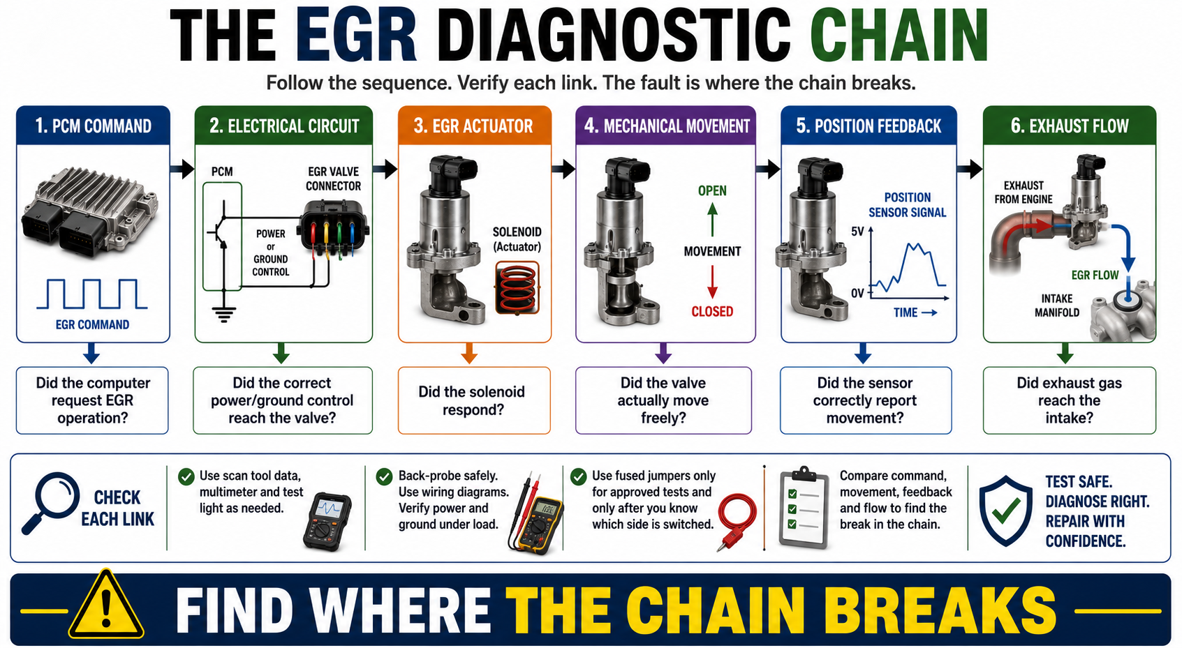
Think about the EGR system as a chain:
PCM Command → Electrical Circuit → EGR Actuator → Mechanical Movement → Position Feedback → Exhaust Flow
Work through that chain in order.
Did the PCM request EGR operation?
If yes, did the correct electrical control reach the valve?
If yes, did the valve physically move?
If yes, did the position sensor accurately report that movement?
If yes, did exhaust gas actually reach the intake?
That method is much more powerful than replacing components based solely on trouble codes.
It also applies to many other computer-controlled automotive systems.
Why a Test Light Still Belongs in an Automotive Electrical Kit
Modern vehicles contain sophisticated electronics, but that does not make the traditional automotive test light obsolete.
It makes knowing where to use it more important.
A digital multimeter measures voltage while placing very little load on a circuit. This is ideal for sensor circuits and electronic measurements.
But that extremely low current draw can occasionally hide a high-resistance problem.
Imagine a wire with severe corrosion leaving only a tiny electrical connection. A digital meter may still display close to battery voltage because the meter requires almost no current.
Connect a load and the voltage may collapse.
An appropriate test light can expose that type of problem because the circuit must actually provide enough current to illuminate the bulb.
That makes a test light extremely useful for certain automotive power and ground tests.
It does not mean a conventional test light should be randomly connected to every wire in a modern vehicle.
Communication networks, low-current sensor circuits, electronic reference circuits, and sensitive module outputs require appropriate testing methods.
The tool is not dangerous when properly applied.
Using the wrong tool on the wrong circuit is the danger.
The Most Important Rule: Never Guess at a PCM-Controlled Circuit
Manual testing gives a technician tremendous diagnostic power because it allows a component to be operated independently of a scan tool.
That power comes with responsibility.
Before supplying external power or ground, know exactly what the circuit is designed to receive.
Use the wiring diagram.
Verify the circuit with the meter.
Load-test appropriate power and ground circuits when necessary.
Use fused jumper leads.
When uncertainty remains, disconnect the component from the vehicle electronics and test it independently according to manufacturer specifications.
One careless jumper wire can turn an EGR problem into a damaged PCM.
Understanding the circuit prevents that.
Troubleshooting Common EGR Problems
An EGR valve that never moves should lead you toward actuator power, ground, wiring, solenoid integrity, and mechanical seizure.
A valve that moves normally but produces no feedback should lead you toward the position sensor and its three circuits.
A valve that opens but returns to a different closed position should raise suspicion of carbon buildup or mechanical sticking.
A valve that moves correctly but produces almost no engine reaction during an appropriate flow test should direct attention toward restricted EGR passages.
A valve that repeatedly works after cleaning but begins sticking again should generally be considered a replacement candidate.
An EGR system in which commanded and actual positions disagree should be diagnosed systematically rather than treated as an automatic valve failure.
What This Diagnosis Really Teaches
The EGR valve is only one application of a much larger automotive electrical principle.
Computer-controlled vehicles are filled with actuators, sensors, solenoids, feedback circuits, reference-voltage circuits, switched powers, switched grounds, and electronic drivers.
Once those concepts are understood, diagnosis becomes much less dependent on memorizing individual vehicles.
Instead of asking, “Which part usually causes this code?” the better diagnostic question becomes:
What did the computer expect to happen, what actually happened, and where did the chain break?
That mindset is useful for EGR valves, purge solenoids, variable valve timing solenoids, transmission controls, throttle systems, cooling-fan controls, and many other electronically managed components.
The tools matter.
Understanding what the electricity is supposed to do matters more.
Preparedness Action Plan
Automotive diagnostic knowledge becomes particularly valuable when internet access, repair facilities, replacement parts, or advanced diagnostic equipment are unavailable. A vehicle that cannot be repaired can quickly become a transportation, evacuation, supply, or mobility problem.
Build a basic automotive electrical diagnostic kit containing a quality digital multimeter, appropriate automotive test light, fused jumper leads, back-probing pins, spare fuses, basic hand tools, and vehicle-specific service information.
Store important wiring diagrams and diagnostic information offline rather than assuming they will always be available through an online service.
Learn how to identify battery power, chassis ground, switched power, switched ground, 5-volt reference, sensor ground, and variable signal circuits.
Practice these skills on known-good circuits before attempting advanced manual actuator testing.
Most importantly, learn to diagnose systematically.
Follow the chain from command to circuit, circuit to component, component to feedback, and feedback to actual mechanical operation.
That approach can solve problems even when sophisticated diagnostic equipment is unavailable.
Key Takeaways
An EGR trouble code identifies a problem area, not necessarily a failed EGR valve.
A linear EGR system may combine an electrically operated solenoid with a position sensor, allowing the PCM to both move the valve and verify where it actually went.
Manual testing can be extremely useful when scan-tool bidirectional controls are unavailable or unreliable, but the circuit must be positively identified before external power or ground is applied.
A multimeter and test light perform different jobs. The multimeter is excellent for measuring electronic signals and sensor circuits, while an appropriate test light can help determine whether certain power and ground circuits can carry a load.
If the valve moves but does not return consistently, investigate mechanical sticking and carbon buildup. If the valve moves but feedback does not change, investigate the position sensor and its circuits. If the valve opens but engine operation barely changes during an appropriate flow test, investigate restricted EGR passages.
The most valuable skill is not knowing how to replace an EGR valve.
It is knowing how to prove what failed before replacing anything.
Disclaimer
This material is provided for educational and preparedness-training purposes only. EGR systems, PCM drivers, connector layouts, control strategies, wiring colors, current requirements, voltage specifications, testing procedures, and relearn processes vary significantly by vehicle manufacturer, model, engine, and model year.
Always consult the correct factory service information and wiring diagram before applying external voltage or ground to any computer-controlled circuit. Incorrect jumper-wire placement or testing can damage the PCM, wiring harness, sensors, connectors, EGR valve, or other electronic components and may create a short circuit, fire, vehicle damage, or personal-injury hazard.
Use appropriately rated and fused test equipment, protect yourself from moving engine components and hot exhaust parts, and do not perform manual circuit activation unless the circuit and switching strategy have been positively identified. When uncertain, have the diagnosis performed by a qualified automotive technician.
© Prepping Communities. This content is for informational purposes only and not professional advice. Use at your own risk.
Terms | Privacy | Guidelines