
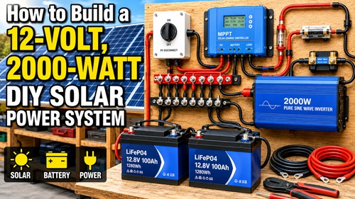
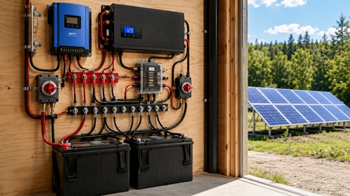
A small off-grid solar system can provide useful electricity when grid power is unavailable, at a remote cabin or workshop, in an RV, or anywhere dependable backup power is needed. A 12-volt system built around a 2,000-watt inverter is a popular size because it can operate many of the same individual appliances and tools normally plugged into a household outlet, while remaining small enough for a knowledgeable DIYer to build.
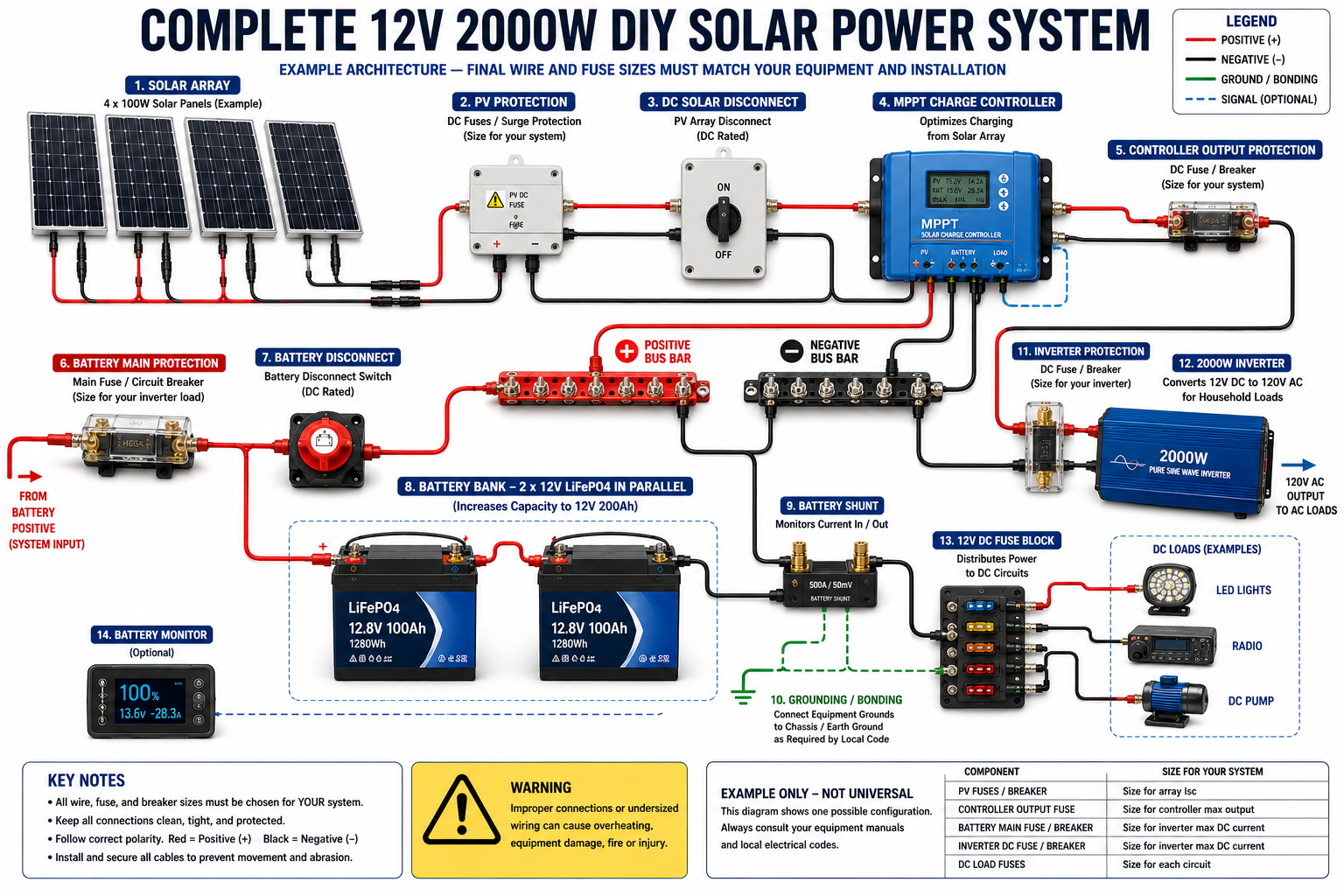
The system covered here uses the same basic architecture demonstrated in the source video: solar panels feed a charge controller, the charge controller manages charging of a 12-volt battery bank, and an inverter converts stored DC energy into AC electricity. A separate 12-volt fuse block can supply DC equipment directly. The example uses four 100-watt solar panels, a 40-amp charge controller, two 12-volt 100Ah LiFePO4 batteries connected in parallel, and a 2,000-watt inverter.
This is not simply a matter of connecting components together. Wire size, overcurrent protection, disconnects, component ratings, cable length, battery specifications, grounding and connection quality all matter. A mistake in a high-current 12-volt system can overheat wiring or cause a fire. Treat the example values in this project as a starting point rather than universal specifications. Always follow the manuals and specifications for the actual equipment being installed, and use qualified electrical help when the installation falls outside your knowledge or applicable electrical requirements.
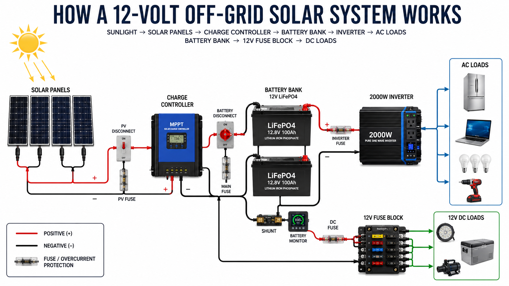
How the System Works
The easiest way to understand an off-grid solar installation is to follow the energy.
SUN → SOLAR PANELS → CHARGE CONTROLLER → BATTERY BANK → INVERTER → AC LOADS
There is also a second path:
BATTERY BANK → 12V FUSE BLOCK → 12V DC LOADS
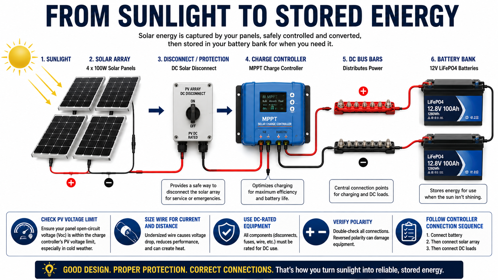
Solar panels produce DC electricity. The charge controller regulates that electricity so the batteries can be charged appropriately. The batteries store the energy until it is needed. The inverter takes 12-volt DC battery power and converts it into AC electricity for compatible appliances, electronics and tools.
The 12-volt fuse block bypasses the inverter for equipment designed to operate directly from 12-volt DC.
Before Building: Calculate the Current
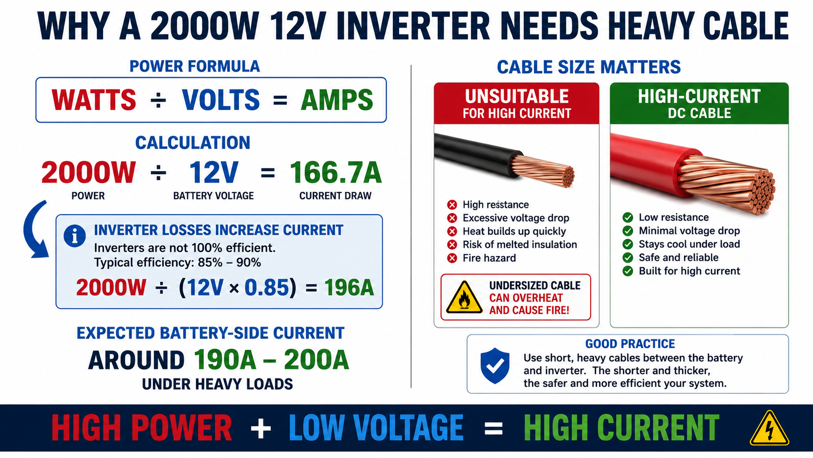
One of the most important concepts in a 12-volt solar system is the relationship between watts, volts and amps.
The basic formula is:
Amps = Watts ÷ Volts
A 2,000-watt load at 12 volts gives:
2,000 ÷ 12 = 166.7 amps
However, an inverter is not perfectly efficient. The source example illustrates this by assuming approximately 85 percent efficiency:
2,000 ÷ 12 ÷ 0.85 ≈ 196 amps
That means the DC side of a 2,000-watt inverter can approach roughly 200 amps under the assumptions used in the example.
This explains why apparently small 12-volt systems use surprisingly heavy cables. Low voltage combined with high power means high current.
Do not automatically use 196 amps as the design current for every 2,000-watt inverter installation. Actual current depends on battery voltage, inverter efficiency, continuous and surge ratings, operating conditions and manufacturer requirements. Use the inverter manufacturer’s specifications when designing the final system.
Components for the Example System
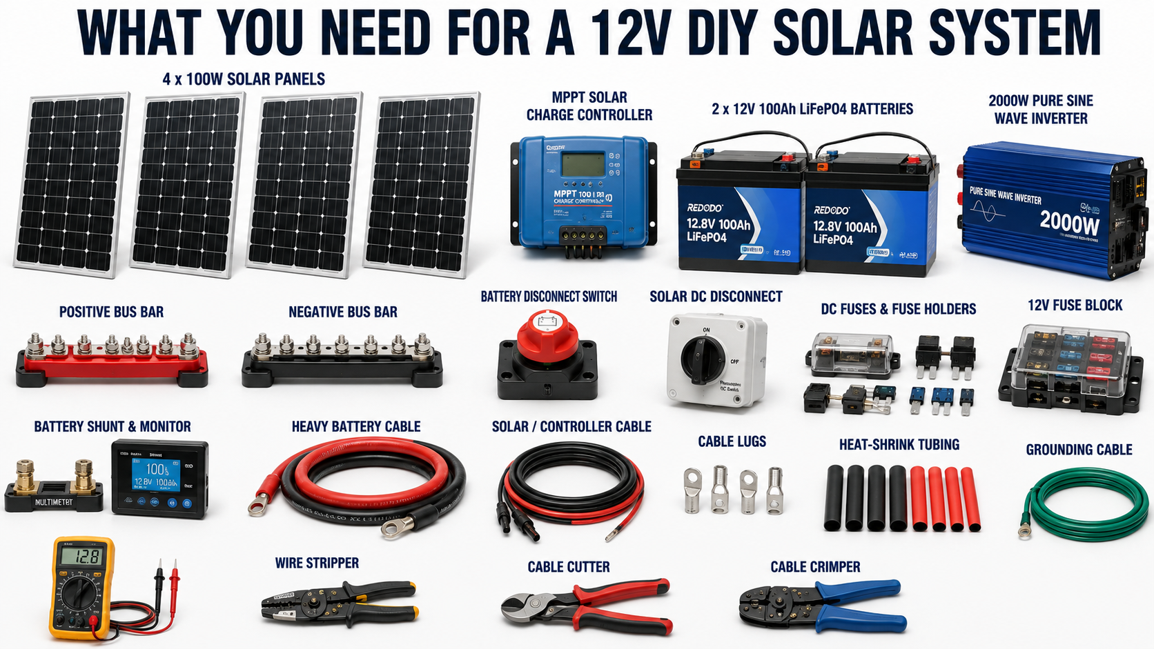
The basic installation requires solar panels, a compatible solar charge controller, a 12-volt battery bank, a 2,000-watt inverter, appropriately rated positive and negative bus bars, battery and solar disconnects, properly selected fuses or breakers, appropriately sized cable, correctly sized cable lugs, heat-shrink tubing and mounting hardware.
The example also includes a shunt and battery monitor, which are useful but not essential to the basic power-conversion process. A 12-volt fuse block provides a convenient way to distribute protected DC circuits.
For the example configuration, the source uses four 100-watt monocrystalline panels feeding a controller rated for up to 520 watts on a 12-volt system.
Step 1 – Draw the System Before Buying Parts
Do not begin by cutting cable.
Draw the complete electrical path first. Put the solar panels, charge controller, batteries, inverter, bus bars, fuses, switches and 12-volt fuse block on paper. Draw positive and negative conductors between them.
Beside every cable, record its expected maximum current and approximate length. Beside each connection, record the terminal or stud size so the correct cable lugs can be purchased.
This planning step can prevent expensive mistakes. The source demonstration specifically recommends diagramming the system before purchasing and laying out components because doing so helps determine wiring, fuse, switch and lug requirements.
Step 2 – Determine Cable Sizes
Every conductor needs to be capable of safely carrying the current expected through it while keeping voltage drop within acceptable limits.
Cable size therefore depends on more than inverter wattage. Consider maximum current, conductor material, insulation temperature rating, installation method, ambient temperature, bundling, allowable voltage drop and total circuit length.
The source demonstration uses 2/0 cable for its high-current inverter circuit and emphasizes increasing conductor size when current or distance requires it.
Do not copy a cable gauge simply because another installation used it. Size the conductor for your installation and the requirements of your equipment.
Step 3 – Select the Correct Lugs
Heavy electrical cable needs properly fitted terminals.
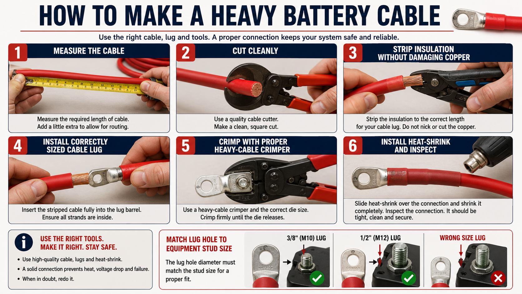
A cable lug must match both the conductor size and the stud or terminal it connects to. A lug designed for the right cable but the wrong stud diameter can create installation problems before the system is ever energized.
Lay out components first and determine how the cable naturally approaches each terminal. Heavy battery cable does not twist easily. When making short cables, orient the lugs so they sit naturally against both terminals without forcing the cable.
Strip only enough insulation for the lug, insert the conductor completely and use a proper crimping tool. Finish the connection with correctly sized heat-shrink tubing.
The source build stresses matching both wire gauge and terminal/post size when choosing lugs.
Step 4 – Install the Inverter Circuit
The inverter is one of the largest loads in the system, so its DC connections deserve particular attention.
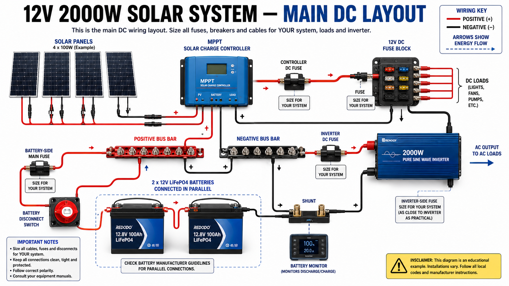
In the source configuration, the positive side is arranged approximately as:
INVERTER → FUSE → POSITIVE BUS BAR → BATTERY DISCONNECT → BATTERY
The negative path is:
INVERTER → NEGATIVE BUS BAR → SHUNT → BATTERY
The shunt is included so a battery monitor can measure current entering and leaving the battery bank.
Mount components so the high-current cable runs can remain short and direct. Heavy cable can place considerable mechanical stress on terminals if components are positioned poorly.
The example uses a 200-amp inverter fuse and a 275-amp disconnect switch, but those values belong to that particular design. Select protection and disconnect equipment according to the cable, inverter, battery/BMS and applicable manufacturer requirements.
Step 5 – Install the Positive and Negative Bus Bars
Bus bars provide central connection points rather than stacking many conductors directly onto battery terminals.
The positive bus bar can distribute battery power to the inverter and 12-volt distribution system while also receiving charging current from the charge controller. The negative bus bar provides a common return point.
This makes the system cleaner, easier to inspect and easier to expand.
Use bus bars rated for the maximum current the installation can produce or consume. Protect exposed positive conductive surfaces against accidental contact with tools or other conductive objects.
Step 6 – Connect the Solar Array to the Charge Controller
The example system uses four 100-watt monocrystalline panels connected in series.
Series wiring increases array voltage while current remains approximately the same as a single panel. Parallel wiring behaves differently, increasing available current while voltage remains approximately the same. The correct configuration depends on the charge controller’s PV input limits and the panels’ electrical specifications.
Never assume four panels can safely be placed in series simply because they are each rated at 100 watts. Determine the array’s maximum expected open-circuit voltage, including cold-weather conditions, and make certain it remains within the controller’s PV voltage limit.
The source installation places overcurrent protection and a DC-rated solar disconnect between the panels and charge controller. Its particular panels have a listed short-circuit current of 5.21 amps, and the example uses a 10-amp inline MC4 fuse after applying its chosen sizing method.
Your panel specifications may be completely different.
The general path is:
SOLAR ARRAY → PV PROTECTION AS REQUIRED → DC DISCONNECT → CHARGE CONTROLLER
The disconnect makes it possible to isolate the solar array while servicing the rest of the system.
Step 7 – Connect the Charge Controller to the Battery System
The charge controller has two sides: PV input from the solar array and battery output toward the battery system.
In the example, the controller is rated for 40 amps. The source uses 8-gauge conductors and a 40-amp fuse on its controller circuit.
Again, do not automatically duplicate those numbers. Follow the charge-controller manufacturer’s conductor and overcurrent-protection specifications.
Keep the battery-side controller wiring reasonably short, protect the positive conductor appropriately and confirm polarity before making connections.
Many controllers also require a particular connection and disconnection sequence. Follow the manufacturer’s manual rather than assuming that PV or battery power can be connected in any order.
Step 8 – Install the 12-Volt Fuse Block
Not every load needs the inverter.
LED lighting, pumps, communications equipment and other compatible 12-volt equipment can often operate directly from the DC system through a fuse block.
Connect the fuse block to the bus bars using appropriately sized conductors and protect its supply conductor according to its allowable current and conductor capacity. Then protect individual branch circuits with correctly selected fuses.
The source’s fuse block is rated for up to 125 amps, although the demonstration intentionally plans to use substantially less current.
A better general design principle is simple:
Design the feeder and its protection for the actual installation rather than relying on the expectation that nobody will ever add a larger load later.
Step 9 – Prepare and Connect the Battery Bank
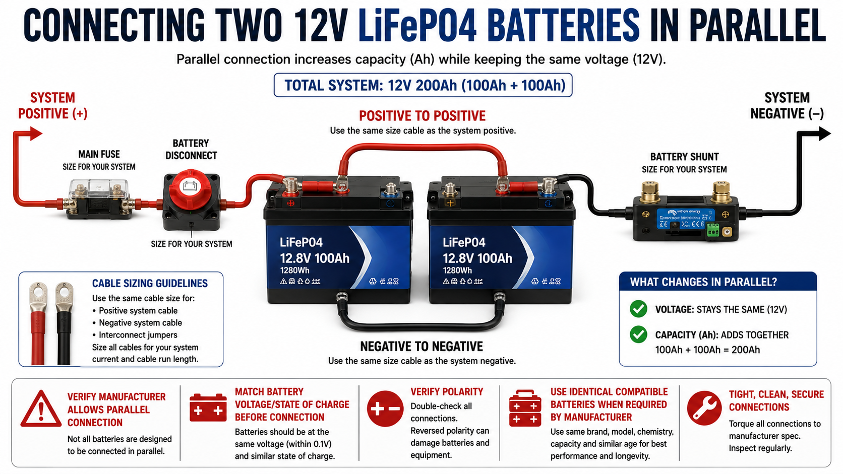
The example uses two 12-volt 100Ah LiFePO4 batteries connected in parallel. Parallel connection maintains a nominal 12-volt system while increasing available amp-hour capacity.
Before paralleling batteries, verify that the manufacturer permits parallel operation, that the batteries are compatible, and that their state of charge and voltage meet the manufacturer’s requirements for connection.
The source checks battery voltage before joining its two batteries and advises bringing them to matching states before parallel connection.
Keep the main battery disconnect OFF while making the final connections.
For a two-battery parallel bank, attention should also be given to balanced current paths. In the source installation, the system positive is taken from one battery and system negative from the other.
The main battery protection should be positioned appropriately near the battery power source so a downstream short cannot turn the battery cable into an uncontrolled heating element.
Step 10 – Install the Battery Monitor and Shunt
A battery monitor is optional, but it provides much more useful information than simply looking at battery voltage.
A shunt measures current flowing into and out of the battery. For it to work correctly, the system must be arranged so the loads and charging sources are measured through the shunt according to the monitor manufacturer’s instructions.
This allows the monitor to estimate battery use, charging current and remaining capacity.
Step 11 – Ground the System Correctly
Grounding is installation-specific and should not be treated as a universal one-wire solution.
A system installed in an RV or van has different considerations from one installed in a detached shed, cabin or permanent structure. Inverter AC grounding and bonding requirements can also vary with inverter design and installation.
The source demonstrates grounding connections on its inverter and charge controller and discusses vehicle chassis and shed grounding arrangements.
Use the inverter, charge-controller and battery manufacturers’ instructions and the electrical requirements applicable to the installation. If there is uncertainty about neutral-ground bonding, chassis bonding, grounding electrodes or permanent AC wiring, use a qualified electrician.
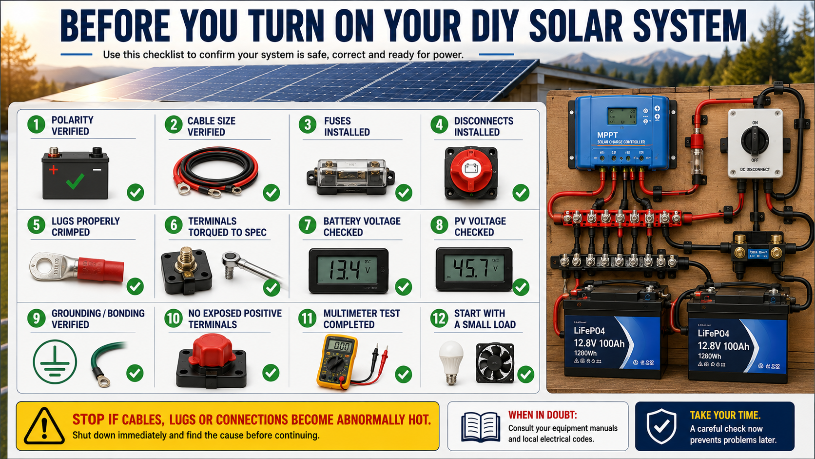
Step 12 – Inspect Everything Before Energizing
Do not turn the system on immediately after tightening the last connection.
Trace every positive conductor from beginning to end. Then trace every negative conductor. Confirm that no positive and negative terminals have been reversed.
Check every fuse and breaker against the conductor and equipment it protects.
Check that cable lugs are fully crimped, terminals are properly tightened to manufacturer specifications, exposed positive terminals are protected, cables cannot rub against sharp surfaces and no tools remain near the battery.
Use a multimeter to verify polarity and expected voltage before connecting sensitive equipment.
Step 13 – Power Up in the Correct Sequence
The correct startup sequence depends on the equipment, particularly the charge controller.
Follow the manufacturers’ instructions.
Do not assume the solar panels should be connected first. Many controllers specify that the battery should be connected before PV so the controller can establish the system voltage correctly.
Begin testing with minimal loads rather than immediately demanding 2,000 watts.
Step 14 – Test the Inverter
Turn on the inverter and verify its output before connecting valuable equipment.
Start with a small, known load. Observe the battery monitor and inverter display.
Increase the load gradually while watching for abnormal voltage drop, inverter alarms, unusual smells, buzzing, loose connections or unexpected heating.
The source demonstration tests the inverter and subsequently checks its cables and lugs for abnormal warmth.
Connections that become unexpectedly hot require investigation. Do not continue operating a questionable circuit simply because the inverter still works.
Understanding What a 2000-Watt Inverter Can Actually Do
A 2,000-watt inverter does not mean there are 2,000 watts available indefinitely.
The battery bank determines how much energy is stored.
Two 12-volt 100Ah batteries connected in parallel provide approximately:
12V × 200Ah = 2,400Wh
That is a simplified nominal-energy calculation. Actual usable AC energy will be lower because of inverter losses, battery limits, wiring losses, temperature, state of charge and other factors.
This distinction is important:
Watts describe power.
Watt-hours describe stored energy.
A 2,000-watt inverter describes how much power the inverter can deliver within its ratings. It does not describe how long the battery can sustain that load.
This is why a refrigerator, communications equipment and lighting may be practical for extended periods while a large electric heater can consume the same battery reserve remarkably quickly.
Common DIY Solar Mistakes
One of the most dangerous mistakes is sizing components independently. The battery, BMS, inverter, conductors, fuses, switches, bus bars and terminals form one high-current electrical system. The safe capacity of one component does not compensate for an underrated component somewhere else.
Another common problem is protecting equipment while forgetting the wiring. A fuse is fundamentally there to interrupt dangerous current before downstream conductors and components are damaged. Its rating and placement therefore matter.
Long cable runs can also create problems. Even when a conductor can carry the current without overheating, excessive voltage drop can reduce inverter performance.
Poor crimps are another source of trouble. A heavy cable with an improperly installed lug can create resistance concentrated at the connection, producing heat even though the cable itself is correctly sized.
Finally, avoid building directly from somebody else’s parts list. Two systems described as “12V 2000W solar systems” can require different components because their batteries, inverters, solar arrays, controllers, cable lengths and installation environments differ.
Quick-Reference System Layout
SOLAR SIDE
Solar Panels
↓
PV Protection as Required
↓
DC Solar Disconnect
↓
Charge Controller
↓
Protected Battery-Side Controller Circuit
↓
Bus Bars / Battery System
BATTERY SIDE
12V Battery Bank
↓
Main Battery Overcurrent Protection
↓
Battery Disconnect
↓
Positive Bus Bar
Negative Battery Connection
↓
Shunt
↓
Negative Bus Bar
AC SIDE
Positive + Negative Bus Bars
↓
Protected Inverter Circuit
↓
2000W Pure Sine Wave Inverter
↓
AC Equipment
12V SIDE
Bus Bars
↓
Protected Fuse-Block Feeder
↓
12V Fuse Block
↓
Individually Fused 12V Circuits
Preparedness Action Plan
Before purchasing equipment, decide what the solar system actually needs to power. Write down each essential appliance or device, its wattage, how many hours per day it may operate and whether it requires AC or 12-volt DC power. This determines whether a 2,000-watt inverter and approximately 2.4kWh nominal battery bank are appropriate or merely arbitrary numbers.
Next, draw the entire installation. Identify every power source, conductor, fuse, disconnect, bus bar and load. Calculate expected current, determine cable lengths and check the specifications of every component against the equipment manufacturers’ requirements.
Build the system methodically rather than rushing toward the moment when the inverter turns on. Make and inspect each cable, protect circuits appropriately, verify polarity, keep high-current cable runs short, label the installation and test progressively.
A well-designed off-grid solar system is more than a collection of panels and batteries. It is a small electrical power system. Understanding how energy moves through it makes the system easier to build, troubleshoot, repair and adapt when replacement parts or professional assistance may not be immediately available.
Key Takeaways
A 12-volt, 2,000-watt solar installation can deliver substantial power, but doing so requires very high DC current. That high current is why heavy conductors, properly made connections, suitable bus bars, correctly selected overcurrent protection and reliable disconnects are so important.
Solar panels generate the energy, the charge controller manages charging, batteries store energy and the inverter makes that stored energy useful to AC equipment. A 12-volt fuse block can supply compatible DC equipment without converting battery power to AC first.
Most importantly, do not simply duplicate somebody else’s wire gauges and fuse ratings. Learn the reasoning behind them, consult the specifications for the actual equipment being installed and design the system around its real loads, distances and environment.
That knowledge is what makes a DIY solar installation maintainable when the internet, grid power or outside assistance is unavailable.
© Prepping Communities. This content is for informational purposes only and not professional advice. Use at your own risk.
Terms | Privacy | Guidelines