
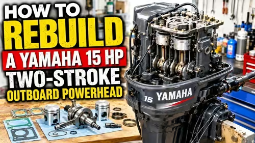
A small two-stroke outboard can remain useful for decades because the basic engine is relatively simple, many components can be replaced individually, and much of the work can be performed with ordinary mechanical tools. For preparedness, this makes a small outboard particularly valuable. A dependable 15-horsepower motor can support fishing, transportation, supply movement, remote-property access, and emergency travel anywhere waterways provide an alternative to roads.
Knowing how to operate an outboard is useful. Knowing how to keep one running is considerably more valuable.
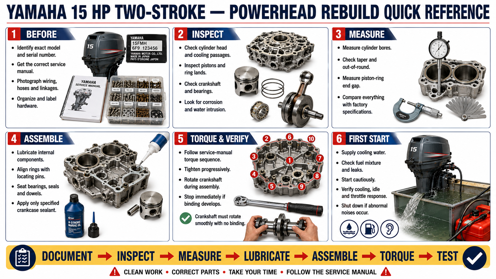
This guide explains the general process of rebuilding a Yamaha 15 HP two-stroke outboard powerhead when the engine block has been damaged but other internal components remain potentially serviceable. The objective is not simply to describe how parts come apart and go back together. It is to teach the inspection, measurement, organization, and mechanical reasoning required to determine whether those parts should be reused in the first place.
IMPORTANT: Obtain the factory service manual or an appropriate professional service manual for the exact model and serial number before beginning. Torque values, clearances, piston-ring specifications, sealants, assembly procedures, ignition settings, and other requirements can vary between engines and production years. Specifications in a guide, video, forum, or manual for a similar engine should never automatically be assumed to apply to yours.
Before You Begin
Difficulty: Advanced
Experience recommended: Previous small-engine repair experience. A first-time engine rebuilder should ideally perform the job with someone experienced in two-stroke engine rebuilding.
Estimated time: One full day for an experienced mechanic under ideal conditions; potentially several days for a first rebuild, particularly when cleaning, measuring, sourcing parts, repairing corrosion, or troubleshooting are required.
Workspace: Clean, well-lit bench with enough room to organize parts without stacking components on top of one another.
Special equipment: Accurate torque wrench, feeler gauges, bore-measuring equipment, precision straightedge, and suitable measuring tools.
Do not rush this repair. A small mistake involving a piston ring, bearing, crankshaft seal, locating dowel, gasket surface, fastener torque, or crankcase seal can undo the entire rebuild.
If you cannot accurately measure components, identify questionable bearings, determine correct ring orientation, or verify manufacturer specifications, stop and get assistance before proceeding.
Safety
Disconnect the spark-plug leads and fuel supply before beginning disassembly.
Work in a well-ventilated area when using gasoline, solvents, cleaners, sealants, or other chemicals. Keep ignition sources away from fuel and solvent vapors.
Wear eye protection when using wire brushes, compressed air, pullers, impact tools, or chemicals.
Use gloves where appropriate, particularly when handling solvents and sharp components.
Support the outboard securely before removing major components. Never rely on an unstable stand or improvised support while applying significant force to fasteners.
Be especially careful around the flywheel and ignition system. Some ignition components can retain or generate substantial electrical voltage.
Never operate a water-cooled outboard without an adequate cooling-water supply.
Understanding the Repair
A cracked cylinder block does not automatically mean the entire outboard must be discarded.
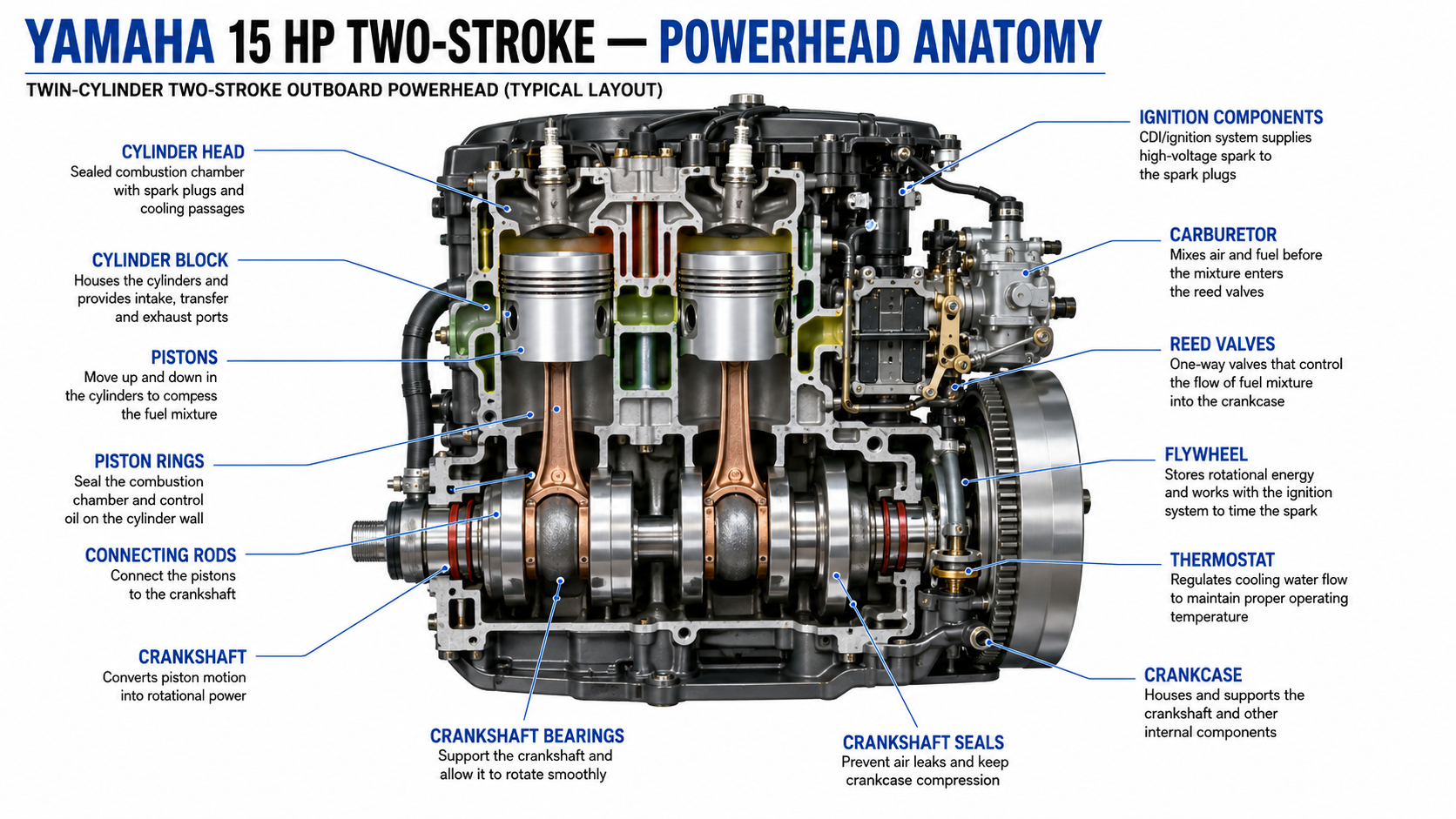
Depending on the failure, the crankshaft, connecting rods, pistons, cylinder head, carburetor, recoil starter, ignition components, flywheel, linkages, fasteners, and other components may remain serviceable.
Those components can potentially be transferred to a replacement block.
The important word is potentially.
A rebuild should never be approached as simply moving everything from the old block into the new one. Every reusable component should earn its way into the rebuilt engine through inspection and, where appropriate, measurement.
Internal corrosion, damaged bearings, excessive wear, broken rings, distorted surfaces, damaged pistons, or evidence of previous incorrect repairs can completely change the scope of the project.
The first goal is therefore not rebuilding.
The first goal is determining what remains usable.
Tools and Supplies
Before dismantling the engine, obtain the correct service information and organize the necessary equipment.
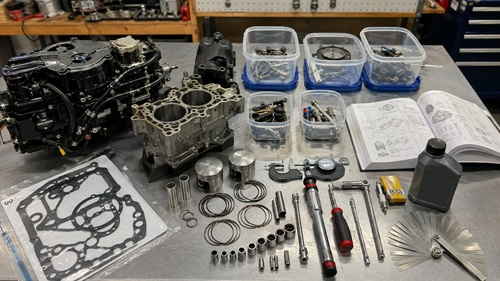
Typical tools include a metric socket and wrench set, screwdrivers, pliers, rubber or soft-faced mallet, torque wrenches covering the required torque ranges, feeler gauges, precision straightedge, bore gauge or suitable internal measuring equipment, micrometers or other sufficiently accurate measuring tools, cleaning brushes, parts trays, solvent-safe containers, and good lighting.
Consumable supplies can include clean shop towels, appropriate cleaning solvent, two-stroke oil or assembly lubricant, manufacturer-approved crankcase sealant, penetrating oil, thread products where specifically required, and fresh fuel for testing.
Replacement parts will normally include the required gasket set, piston rings, and accessible crankshaft seals. Depending on what inspection reveals, the rebuild may also require bearings, a thermostat, sacrificial anode, Woodruff key, locating dowels, damaged fasteners, hoses, fuel-system components, or other parts.
Do not order major internal parts by appearance alone.
Verify part numbers against the exact engine model whenever possible.
Step 1 – Document the Engine Before Disassembly
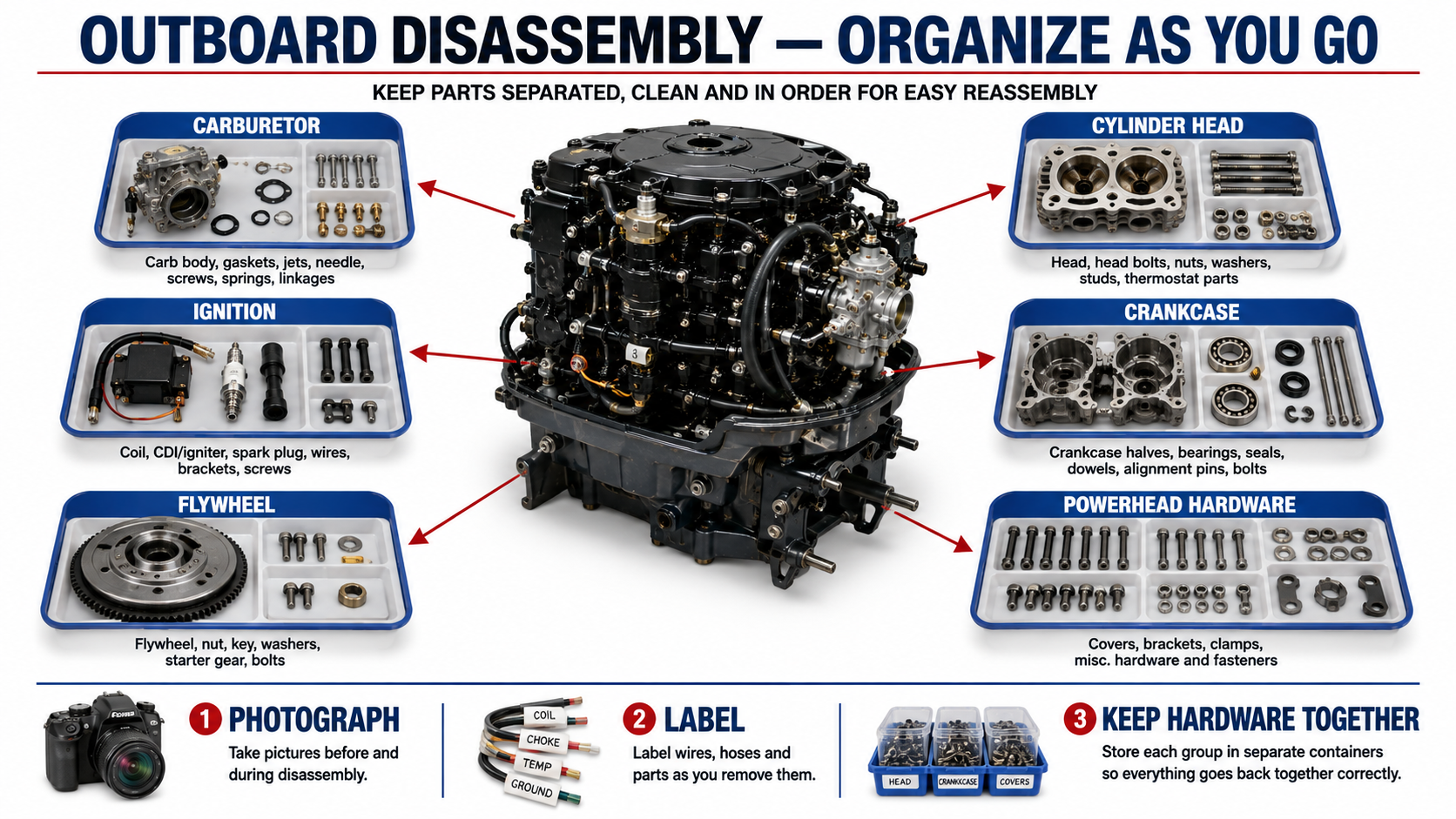
Before removing anything, photograph the complete powerhead.
Take pictures from the front, rear, both sides, and above. Photograph electrical connections, fuel lines, throttle linkage, shift linkage, ignition components, hose routing, brackets, and anything else that may become difficult to remember later.
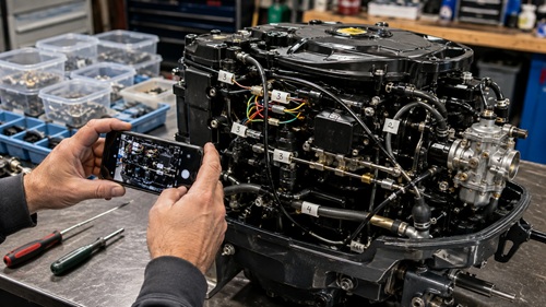
Take additional photographs throughout the teardown.
Label wires and hoses if there is any possibility of confusion.
Mechanical memory is unreliable after dozens of components have been removed.
Documentation turns reassembly from guesswork into reference.
This becomes even more important in preparedness situations where an engine may remain disassembled while parts are being sourced.
Step 2 – Perform an Initial Inspection
Examine the complete engine before dismantling it.
Look for cracks, corrosion, damaged mounting points, loose or missing hardware, deteriorated wiring, damaged fuel lines, evidence of overheating, and signs of previous repair work.
Rotate the engine manually when possible.
Feel for binding, grinding, roughness, or unusual resistance.
Inspect visible cooling passages and external components.
Look closely for evidence that the engine has previously been dismantled. Missing keys, loose fasteners, excessive sealant, mismatched hardware, damaged bolt heads, or incorrectly routed components can indicate earlier repairs.
Never assume the previous person assembled the engine correctly.
Step 3 – Organize Parts as They Come Off
Organization is one of the easiest ways to prevent mistakes.
Use separate labeled containers or bags for different assemblies:
Carburetor hardware.
Recoil starter hardware.
Ignition components.
Cylinder-head hardware.
Crankcase fasteners.
Flywheel components.
Powerhead mounting hardware.
Covers and cooling-system components.
Small outboard fasteners can look almost identical while differing slightly in length, shoulder dimensions, thread, or intended location.
Do not throw everything into one container.
Keep washers, spacers, shims, locating dowels, and clips associated with their original assemblies whenever possible.
Step 4 – Remove the External Components
Remove the components surrounding the powerhead according to the service-manual procedure.
Depending on the engine, this may include the carburetor, recoil starter, ignition components, electrical connections, fuel lines, shift linkage, throttle components, exhaust-related components, and various covers.
Do not pull electrical connectors apart by their wires.
Inspect components as they are removed.
A cracked fuel hose, damaged connector, corroded terminal, or loose linkage discovered now can be repaired before the engine returns to service.
Step 5 – Remove the Flywheel
Remove the flywheel retaining hardware using the correct procedure.
Use the appropriate flywheel puller when required.
Avoid aggressively prying against the flywheel or crankcase. Improvised removal methods can damage components that were perfectly serviceable before the repair began.
Once the flywheel has been removed, inspect the Woodruff key and keyway.
The key helps maintain the proper mechanical relationship between the crankshaft and flywheel.
If the key is missing, damaged, or questionable, replace it with the correct part.
Store the flywheel where the magnets and machined surfaces cannot be damaged.
CHECKPOINT
Before continuing, make sure you know:
- Where the flywheel key is.
- Which fasteners belong to the flywheel assembly.
- How the ignition components were positioned.
- Whether anything appears to have been previously assembled incorrectly.
Correct those problems during the rebuild rather than duplicating them.
Step 6 – Remove the Cylinder Head
Loosen the cylinder-head bolts progressively rather than applying maximum force to one fastener immediately.
Older marine engines can develop substantial corrosion around cylinder-head bolts, especially after saltwater operation.
A broken bolt can transform a straightforward rebuild into a much more difficult repair.
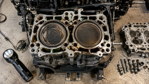
Once the head has been removed, examine the combustion chambers, piston crowns, cylinder walls, head gasket, and cooling passages.
Look for scoring, corrosion, pitting, unusual deposits, evidence of overheating, and signs of water intrusion.
Water inside a cylinder is particularly important.
Do not merely clean it away.
Determine why it was there.
Step 7 – Inspect the Cooling System
A rebuilt engine can be destroyed quickly if the cooling system is not working correctly.
Inspect accessible water passages for corrosion, sediment, salt deposits, or other restrictions.
Inspect the thermostat if equipped.
A thermostat that is stuck closed can cause overheating. A questionable thermostat should be tested or replaced according to the service-manual procedure.
Inspect the sacrificial anode if one is fitted to the powerhead.
A heavily consumed anode should be replaced.
Cooling-system inspection is part of an engine rebuild, not an unrelated maintenance job.
There is little value in rebuilding the powerhead and then allowing it to overheat because a cooling problem was ignored.
Step 8 – Inspect the Cylinder Head
Clean the cylinder-head mating surface carefully.
Do not aggressively grind or sand away material simply to make the surface look clean.
Check the head for damage, corrosion, and distortion.
Use a precision straightedge and the inspection method specified by the manufacturer to determine whether the mating surface remains within allowable limits.
A warped cylinder head can prevent the new head gasket from sealing properly.
Also inspect combustion chambers and cooling passages.
If the head falls outside manufacturer specifications, repair or replace it rather than hoping a new gasket will compensate.
Step 9 – Split the Crankcase
Remove the crankcase fasteners and record their locations.
Separate the crankcase halves carefully.
Do not drive screwdrivers deeply between precision mating surfaces. Gouges can create sealing problems later.
Watch for locating dowels, shims, thrust washers, bearing locators, and other small components as the crankcase separates.
Photograph their locations before removing them.
A tiny washer that appears insignificant may control an important clearance.
STOP IF:
A crankcase half refuses to separate despite all identified fasteners being removed.
Do not simply apply more force.
Check the service manual again for hidden fasteners, locating features, corrosion, or another component preventing separation.
Step 10 – Remove the Crankshaft and Pistons
Remove the crankshaft, connecting rods, and pistons according to the engine design.
Support the assembly carefully.
Do not allow connecting rods, bearing surfaces, or pistons to strike the bench.
Once removed, place the assembly on a clean surface.
Do not immediately transfer it into the replacement block.
This is one of the most important inspection opportunities in the entire rebuild.
Step 11 – Inspect the Crankshaft and Bearings
Rotate each accessible bearing slowly by hand.
Feel for roughness, clicking, binding, excessive play, or unusual noise.
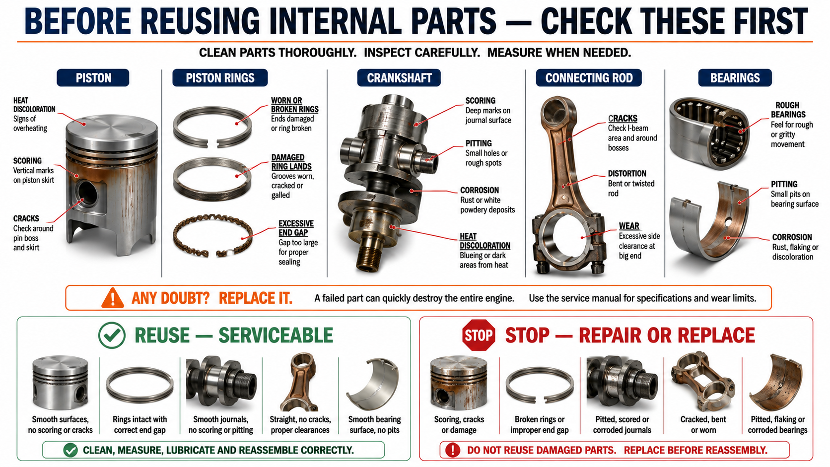
Inspect crankshaft surfaces for corrosion, discoloration, scoring, and wear.
Inspect connecting rods and piston-pin areas.
Water intrusion deserves particular attention.
A bearing can still rotate while corrosion is developing internally.
If a bearing feels questionable, investigate it before continuing.
Installing a questionable bearing because replacing it is inconvenient can result in having to dismantle the entire engine again – or losing the engine completely.
Step 12 – Clean and Inspect the Pistons
Remove carbon and contamination carefully.
Pay particular attention to the piston-ring grooves.
Carbon trapped inside a groove can prevent a new ring from moving correctly.
Avoid aggressive cleaning methods that remove piston material or damage the ring lands.
Once clean, inspect each piston for cracks, scoring, overheating, damaged ring grooves, worn surfaces, and other defects.
New rings cannot repair a damaged piston.
If the piston is outside specification, replace it.
Step 13 – Inspect the Replacement Block
A replacement block should be inspected just as carefully as the original components.
Do not assume a new aftermarket or replacement casting is automatically correct.
Check the casting for obvious defects.
Verify threaded holes.
Inspect mating surfaces.
Check cooling passages.
Verify that required fittings and mounting points are present.
Compare the replacement block carefully with the original.
Some replacement castings may require fittings or other reusable components to be transferred from the original block.
Do this before assembly begins.
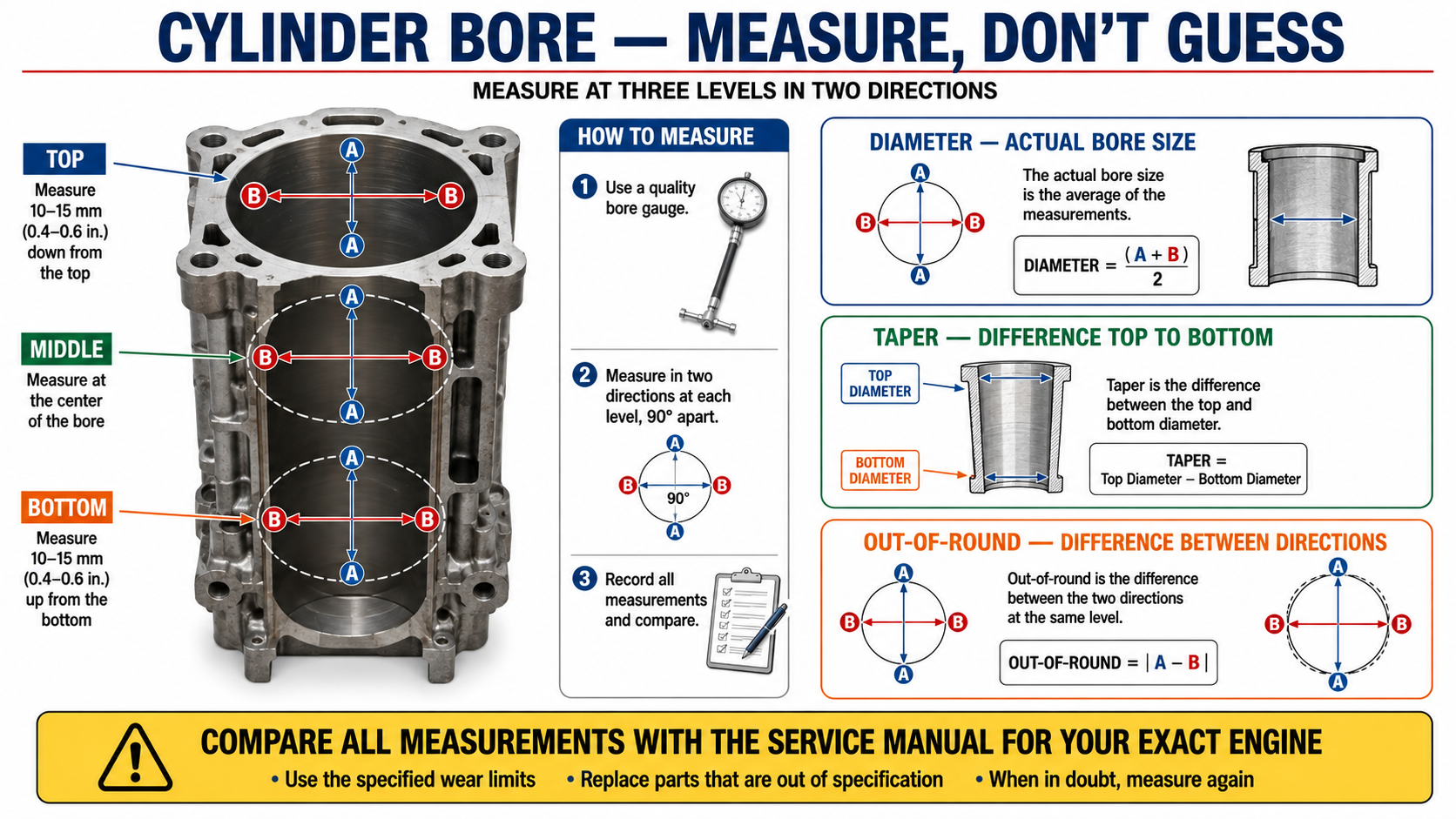
Step 14 – Measure the Cylinder Bores
This is one of the most important stages of the rebuild.
Use a bore gauge, internal micrometer, or another sufficiently accurate method suitable for engine measurement.
Measure each cylinder at multiple heights and in multiple directions.
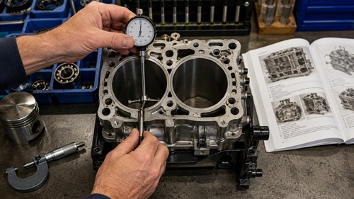
You are not simply determining diameter.
Multiple measurements can reveal:
Taper — the cylinder diameter changes from top to bottom.
Out-of-round — the cylinder is not equally round in all directions.
Excessive clearance — the bore is too large for the intended piston.
Compare all measurements with the manufacturer’s specifications.
DO NOT CONTINUE IF:
A bore falls outside allowable specifications.
Determine whether machining, different pistons, another block, or other corrective work is required.
New piston rings cannot compensate for a fundamentally incorrect cylinder bore.
Step 15 – Check Piston-Ring End Gap
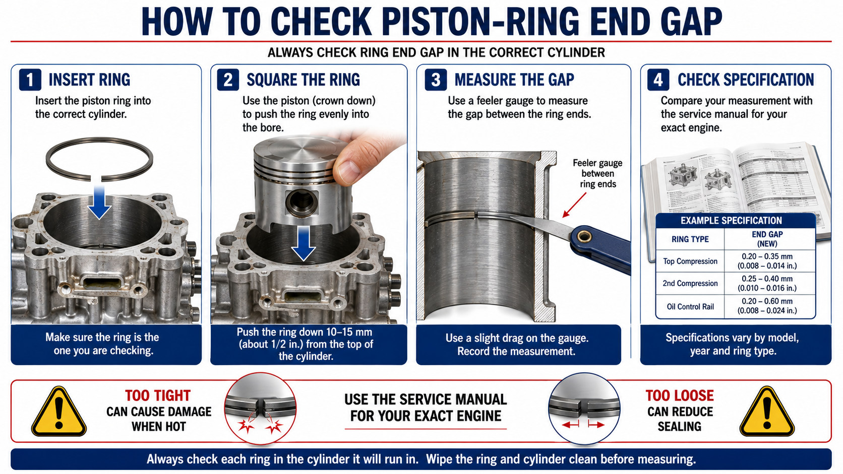
Never assume new piston rings are automatically ready for installation.
Place one ring inside its corresponding cylinder.
Use a piston or appropriate ring-squaring tool to push the ring into the bore so that it sits evenly and squarely.
Use feeler gauges to measure the gap between the two ring ends.
Compare the measurement with the manufacturer’s minimum and maximum specifications.
Repeat the procedure for every ring.
Too little end gap can be dangerous. As the ring heats and expands, the ends can contact each other and create severe cylinder damage.
Excessive gap can reduce sealing and may indicate incorrect rings or excessive cylinder clearance.
VISUAL CHECK
The ring should sit squarely inside the cylinder.
A tilted ring produces a misleading measurement.
Step 16 – Identify Ring Position and Orientation
Do not assume all piston rings are identical.
Inspect their profiles, markings, coatings, and edges.
Determine which ring belongs in each groove and which side faces upward using the service manual and ring manufacturer’s instructions.
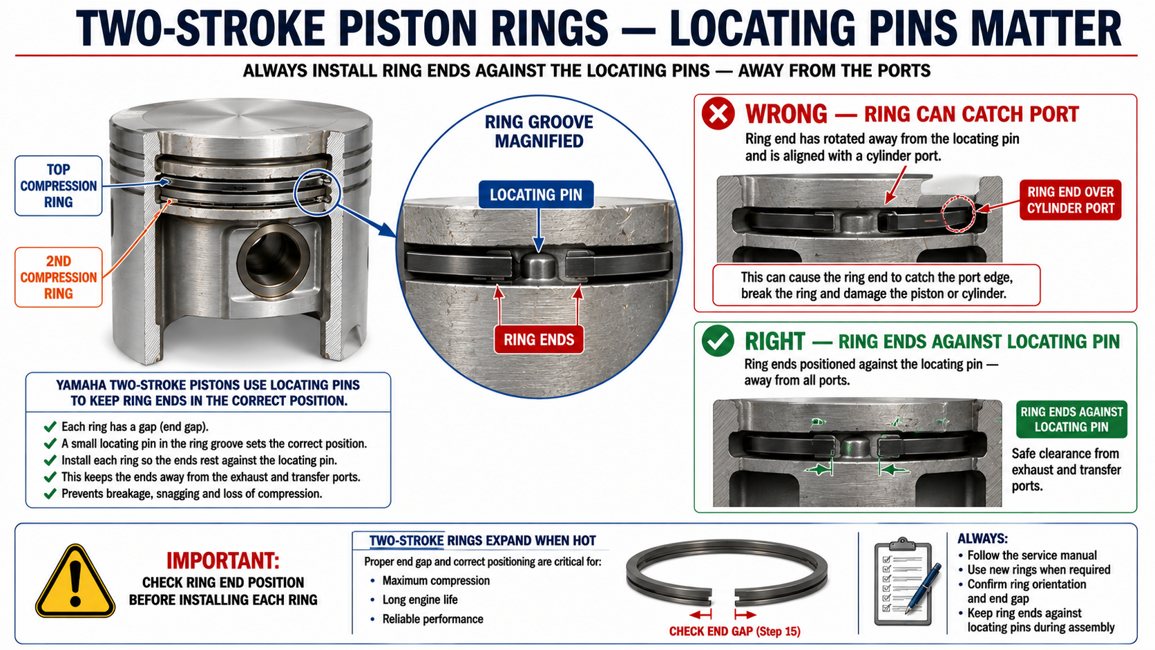
Two-stroke pistons commonly incorporate locating pins in the ring grooves.
These prevent the piston rings from rotating until the ring ends encounter cylinder ports.
Correct ring position is therefore especially important.
Installing a ring incorrectly can cause poor compression or severe engine damage.
Step 17 – Install the Piston Rings
Clean the piston-ring grooves thoroughly before installation.
Lubricate the rings according to the assembly procedure.
Expand each ring only as far as necessary to move it over the piston.
Do not unnecessarily stretch or twist it.
Place each ring into its correct groove and verify that it moves as intended.
Position the ring ends correctly against their locating pins.
Check everything twice.
Piston rings are small components capable of destroying an engine when installed incorrectly.
Step 18 – Replace Accessible Crankshaft Seals
A two-stroke engine depends on a properly sealed crankcase.
Air entering through a damaged crankshaft seal can create poor running, difficult starting, unstable idle, or an excessively lean mixture.
A lean condition can eventually damage the engine.
Replacing accessible crankshaft seals during a major rebuild is therefore inexpensive insurance.
Inspect the seal surfaces before installation.
Lubricate seals where specified.
Install each seal in the correct orientation and to the correct depth.
Protect the sealing lips from sharp crankshaft edges during installation.
Also inspect any small crankcase fittings, vacuum lines, pulse fittings, or other connections.
A missing or poorly sealed fitting can create the same type of unwanted air leak as a failed seal.
Step 19 – Lubricate Internal Components
Never assemble the internal components completely dry.
Apply the appropriate two-stroke oil or specified assembly lubricant to the cylinder walls, pistons, piston rings, connecting-rod bearings, crankshaft bearings, and relevant seal surfaces.
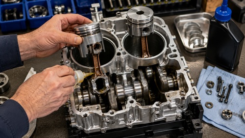
This provides lubrication during the first revolutions before the normal fuel-and-oil mixture reaches every internal component.
Cleanliness is equally important.
Keep dirt, metal particles, abrasive material, shop debris, and lint away from the open crankcase.
One contaminated bearing can undermine hours of careful work.
Step 20 – Install the Pistons and Crankshaft
Position each piston ring correctly against its locating pin.
Guide the pistons carefully into their cylinders.
Do not force them.
If a piston stops, pull back and determine why.
A ring may have shifted, caught an edge, or become incorrectly positioned.
Forcing it can snap the ring or damage the cylinder.
Once the pistons are correctly entering the bores, lower the crankshaft assembly into position according to the engine design.
Work slowly.
This is not a stage where speed provides any advantage.
Step 21 – Seat Bearings and Locating Components
Make sure each crankshaft bearing is fully seated.
Verify the positions of bearing locators, dowels, thrust washers, shims, and other alignment components.
Locating dowels are not optional hardware.
They maintain the intended relationship between components.
Before closing the crankcase, compare the assembly against your photographs and the service-manual diagrams.
Then rotate the crankshaft manually.
It should move smoothly.
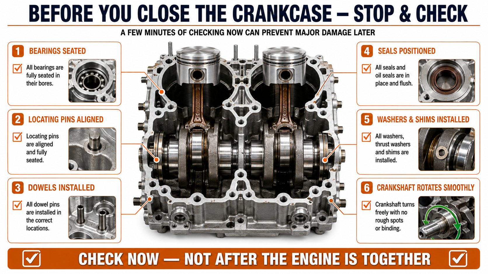
CHECKPOINT
Do not close the crankcase until:
- All bearings are seated.
- Locating pins and dowels are accounted for.
- Required washers and shims are installed.
- Seals are correctly positioned.
- Pistons move correctly.
- The crankshaft rotates smoothly.
Five minutes spent checking now can save several hours later.
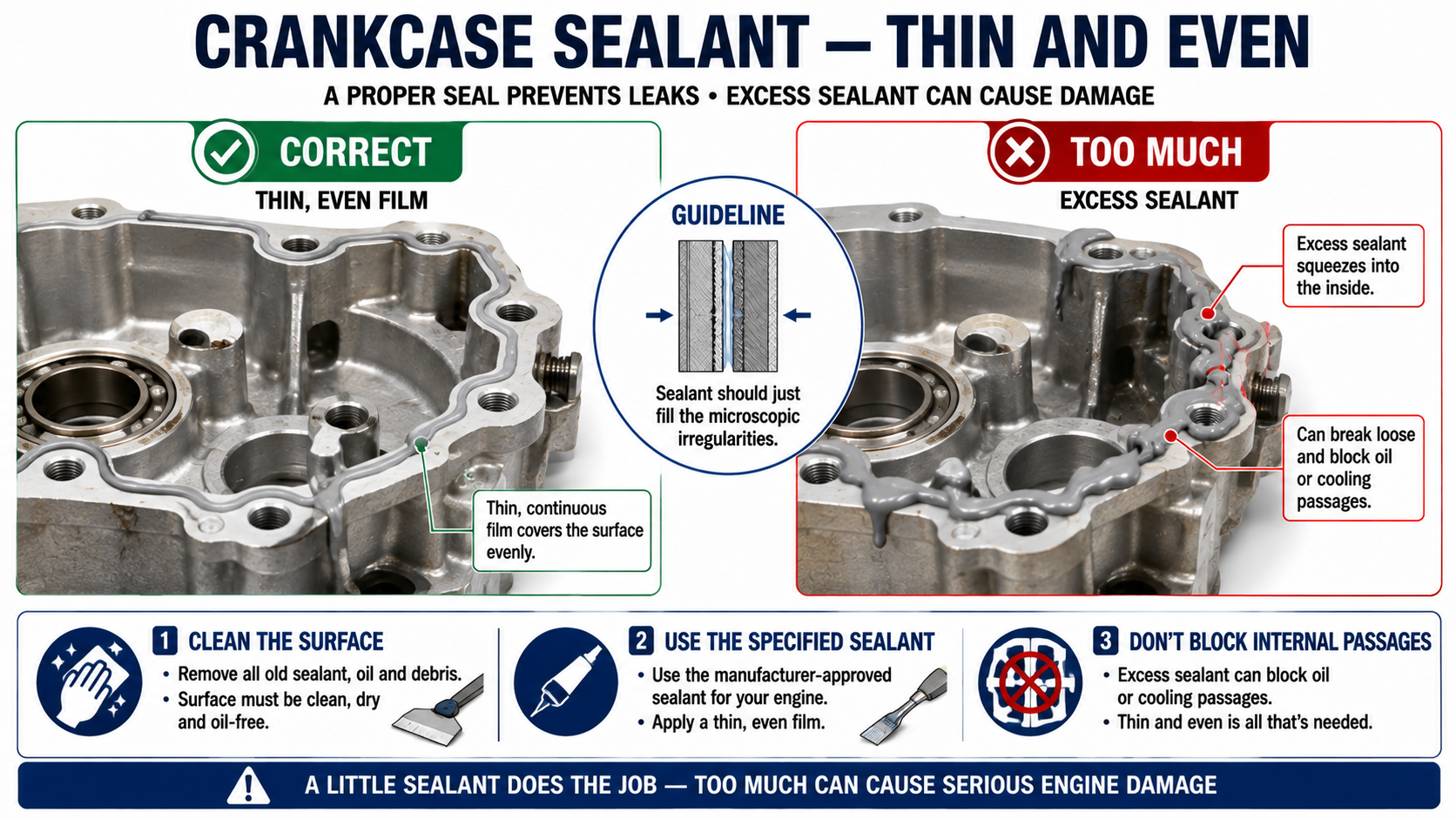
Step 22 – Prepare the Crankcase Mating Surfaces
Clean both crankcase mating surfaces.
Remove old gasket material and sealant without gouging the aluminum.
The surfaces should be clean, dry, and suitable for the sealing method specified by the manufacturer.
Consult the service manual to determine whether sealant is required and which type should be used.
If sealant is specified, apply the required amount.
More is not better.
Excess sealant squeezed inside the engine can interfere with internal passages or break loose later.
Do not automatically substitute ordinary household silicone.
Use a sealant appropriate for the engine and application.
Step 23 – Join the Crankcase Halves
Before bringing the halves together, perform one final inspection.
Check the locating dowels.
Check bearings.
Check seals.
Check washers and shims.
Check the crankshaft.
Check the sealant.
Then carefully lower the crankcase half into position.
Start the fasteners by hand.
The crankcase halves should seat normally.
Never use the bolts to force badly misaligned components together.
If the case will not seat, separate it and find the obstruction.
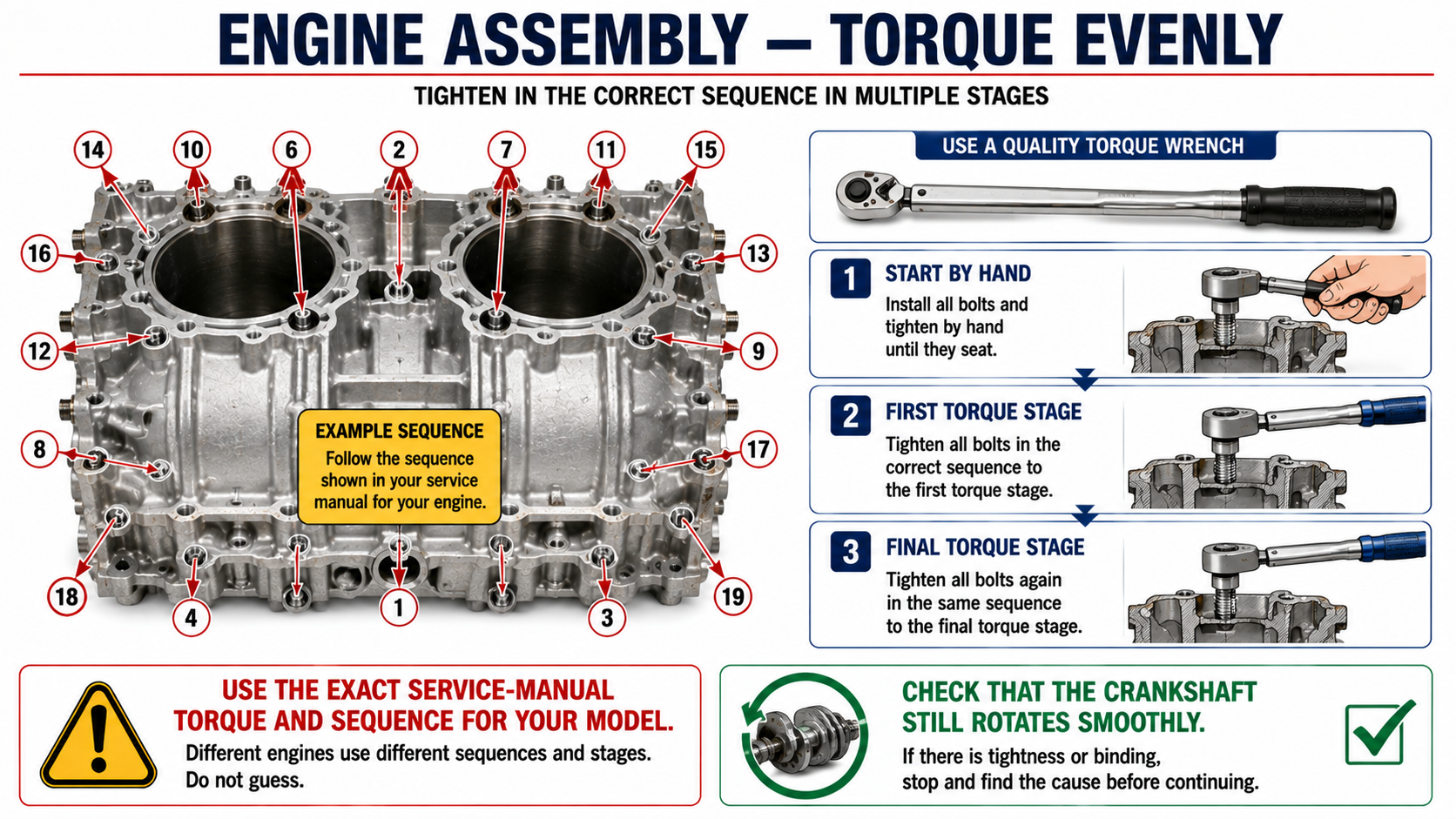
Step 24 – Torque the Crankcase
Use a calibrated torque wrench.
Follow the exact specifications and tightening stages given in the service manual.
If a tightening sequence is specified, follow it.
Where progressive torque stages are required, complete each stage across the assembly before increasing the torque.
Tightening gradually and evenly helps prevent crankcase distortion.
After each major tightening stage, rotate the crankshaft manually.
CRITICAL CHECK
If the crankshaft rotated freely before tightening but becomes noticeably difficult afterward, stop.
Do not assume it will loosen once the engine runs.
Something may be misaligned, incorrectly seated, or improperly loaded.
Correct the problem before continuing.
Step 25 – Reinstall the Sacrificial Anode
Inspect the powerhead anode if equipped.
Replace it if substantially consumed or damaged.
Clean the mounting and contact surface before installation.
The anode must maintain electrical contact with the engine metal to perform its job.
Do not paint the contact area or coat the anode in a way that electrically isolates it.
Anodes are inexpensive compared with the aluminum components they protect.
Step 26 – Install the Head Gasket
Clean the block and cylinder-head mating surfaces.
Verify that both surfaces are suitable for assembly.
Install the correct new head gasket in the proper orientation.
Do not automatically add sealant.
Some head gaskets are designed for dry installation or contain their own sealing material.
Follow the gasket and engine manufacturer’s requirements.
A new gasket installed incorrectly is still an incorrectly installed gasket.
Step 27 – Install and Torque the Cylinder Head
Position the cylinder head carefully.
Start all bolts by hand.
Use the specified tightening sequence and torque stages.
A cylinder head should be drawn down progressively and evenly.
Incorrect torque can cause gasket failure, thread damage, distortion, compression loss, or cooling problems.
After torquing, inspect the assembly visually before moving on.
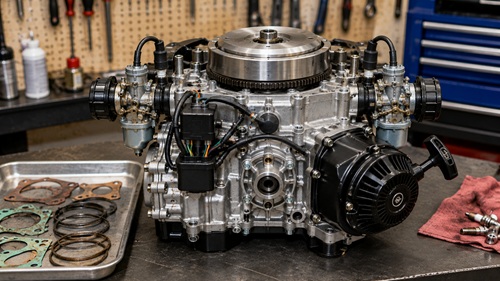
Step 28 – Reassemble the Powerhead
Reinstall the remaining covers, ignition components, reed assembly, carburetor, starter, linkages, electrical connections, and hoses.
Use the photographs and labels created during disassembly.
Replace damaged gaskets rather than attempting to reuse questionable ones.
Check fuel hoses for cracking or deterioration.
Verify that throttle and shift linkages move freely.
Install the correct flywheel key and flywheel according to the service manual.
Torque the flywheel hardware correctly.
Do not guess.
Step 29 – Reinstall the Powerhead on the Outboard
Install a new base gasket when required.
Carefully lower the powerhead onto the remaining outboard assembly.
Make sure shafts, passages, mounting points, and other interfaces align correctly.
Start mounting fasteners by hand before tightening.
Reconnect the fuel system, cooling system, ignition wiring, controls, and other connections.
Before starting the engine, stop and inspect the entire installation.
Look for:
Disconnected wires.
Unattached fuel lines.
Loose clamps.
Forgotten bolts.
Tools near the flywheel.
Incorrectly routed linkages.
Fuel leaks.
Anything capable of contacting a moving component.
Do not allow excitement about the first start to replace inspection.
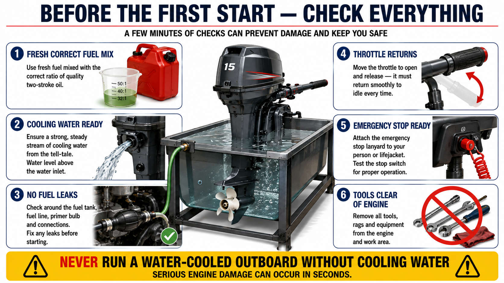
Step 30 – Prepare for the First Start
A water-cooled outboard must have an adequate cooling-water supply before it is started.
Use an appropriate test tank or the flushing method approved for the engine.
Prepare fresh fuel using the correct gasoline-to-two-stroke-oil mixture specified for the motor.
Prime the fuel system.
Check for leaks.
Make sure the throttle can return normally.
Confirm that you can shut the engine down immediately.
Keep the emergency stop mechanism accessible.
Have a suitable fire extinguisher nearby whenever testing gasoline-powered equipment.
Step 31 – Perform the First Start
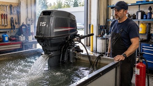
Treat the first start as a diagnostic test.
Start the engine and immediately listen.
You are looking for normal mechanical operation—not maximum RPM.
Listen for knocking, grinding, rattling, scraping, or other abnormal noises.
Confirm cooling-water circulation.
Watch for fuel leaks.
Watch for water leaks.
Look for exhaust escaping from unexpected locations.
Observe the engine carefully.
Do not immediately race a freshly assembled engine.
If something sounds wrong, shut it down.
Finding a problem after thirty seconds is much better than allowing a questionable engine to run for ten minutes.
Step 32 – Check Idle and Running Quality
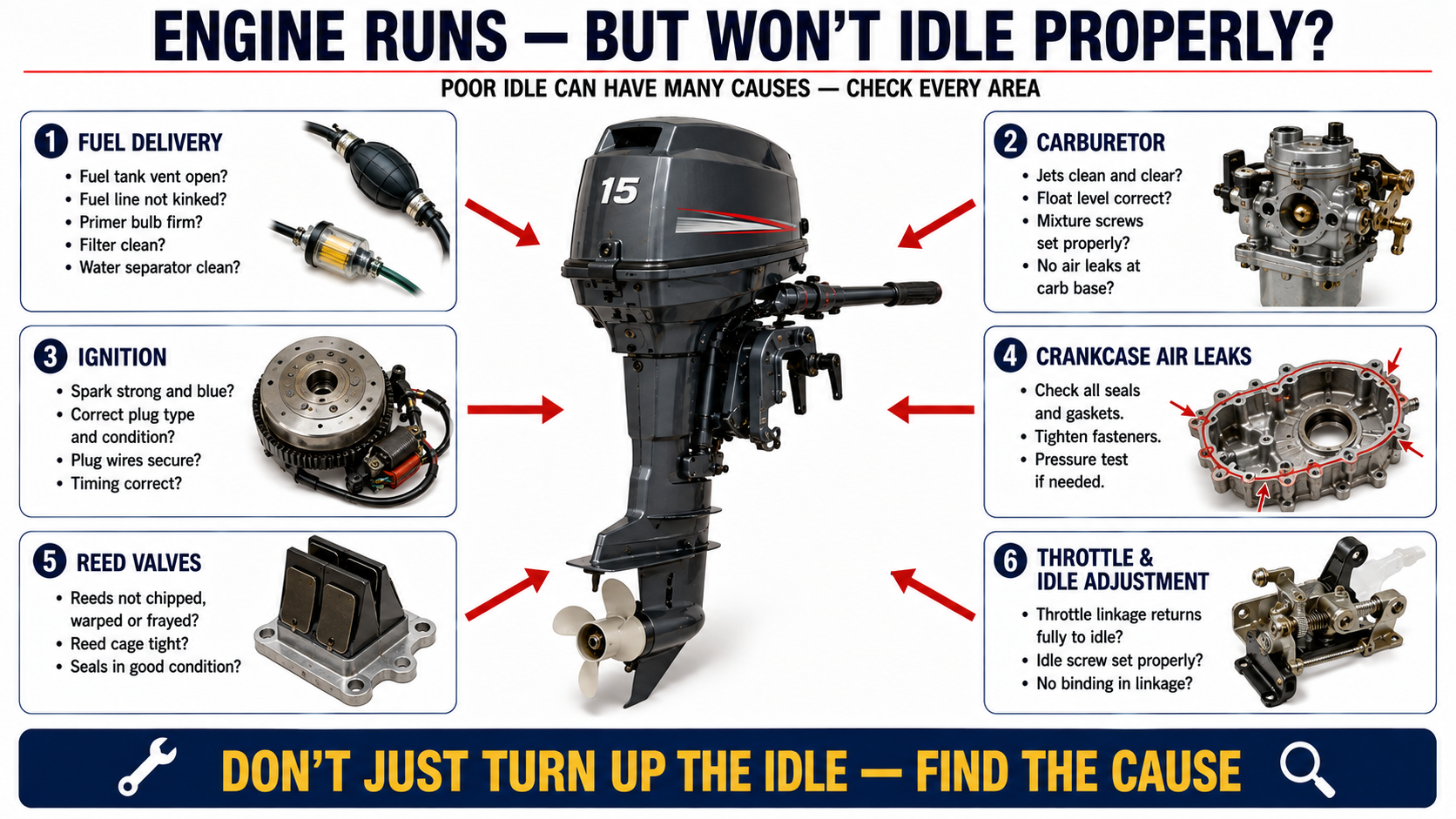
An engine that starts is not necessarily repaired.
It should also idle appropriately, respond to throttle, cool correctly, and operate without abnormal noises or leaks.
If it runs but will not idle properly, continue troubleshooting.
Possible causes can include carburetor contamination or adjustment, incorrect idle settings, fuel-delivery problems, ignition issues, crankcase air leaks, damaged reeds, incorrect linkages, or other mechanical conditions.
Do not hide an underlying problem by simply increasing idle speed.
Diagnose it.
A dependable outboard should start, run, idle, cool, and respond predictably.
Step 33 – Perform a Post-Run Inspection
Shut the engine down after the initial test and inspect it again.
Look for leaks around the cylinder head, crankcase, fuel system, cooling system, and powerhead base.
Check for loose hardware.
Inspect wiring and hoses.
Look for anything that shifted during operation.
Once the engine has cooled, perform any manufacturer-specified post-rebuild checks.
A second inspection frequently catches problems that were invisible before the engine experienced vibration, heat, pressure, and fuel flow.
Common Rebuild Mistakes
The most expensive mistakes in engine rebuilding are often surprisingly small.
Forcing a piston into a cylinder can break a ring.
Forgetting a locating dowel can affect alignment.
Installing a ring backward can cause poor sealing or damage.
Failing to check ring gap can create problems once the engine reaches operating temperature.
Using too much crankcase sealant can contaminate internal passages.
Installing components dry can damage them during the first revolutions.
Guessing torque values can strip threads or distort components.
Reusing questionable seals can create crankcase air leaks.
Ignoring corrosion inside bearings can lead to failure shortly after the rebuild.
Failing to photograph the original assembly can create avoidable confusion during reassembly.
And perhaps the biggest mistake is assuming that because the engine starts, the rebuild is finished.
Starting is only one test.
Dependability is the objective.
Building an Outboard Repair Kit for Preparedness
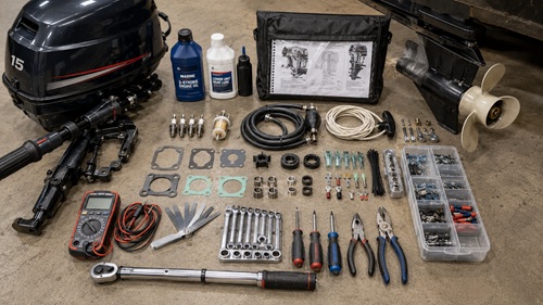
An outboard used as part of a preparedness plan should have basic repair supplies stored with it.
The exact inventory depends on the motor, but commonly useful items include the correct spark plugs, fuel hose, fuel filter, fuel connectors, pull-start cord, common gaskets, seals, spare propeller hardware, appropriate two-stroke oil, lower-unit lubricant, basic electrical repair supplies, common fasteners, and model-specific components known to fail.
Keep the appropriate service manual offline.
Record important part numbers.
Keep wiring diagrams and exploded parts diagrams.
If an electronic manual is stored on a laptop or tablet, keep another copy on removable storage.
A spare part without the knowledge required to install it has limited value.
A manual without the tools required to perform the repair has the same problem.
Preparedness comes from combining parts, tools, documentation, and skill.
Why This Skill Matters for Preparedness
Small outboards can be extremely useful around lakes, rivers, coastal areas, remote cabins, and properties where waterways provide transportation.
In a prolonged disruption, professional repair services and replacement equipment may become difficult to obtain.
Mechanical preparedness therefore means more than owning another motor.
It means understanding the machine well enough to diagnose and repair it.
A person who can measure cylinder wear, evaluate bearings, replace seals, correctly install piston rings, rebuild a powerhead, and troubleshoot the resulting engine possesses a capability that cannot be replaced simply by stockpiling equipment.
These skills also transfer.
Understanding bearings, seals, compression, fuel delivery, ignition, lubrication, fastener torque, gasket surfaces, and mechanical measurement improves the ability to repair generators, pumps, chainsaws, motorcycles, ATVs, and other small engines.
Learning one machine teaches principles that apply to many others.
Preparedness Action Plan
Obtain the correct service manual for every important engine or machine you depend upon and store it offline.
Build a mechanical tool kit that includes proper torque wrenches, feeler gauges, electrical testing equipment, and basic precision measuring tools.
Keep commonly needed maintenance and repair parts for critical equipment.
Learn basic two-stroke troubleshooting before attempting a complete rebuild.
Practice disassembly, carburetor cleaning, ignition troubleshooting, fuel-system repair, compression testing, and routine maintenance before moving into complete powerhead rebuilding.
If possible, learn engine rebuilding alongside an experienced mechanic.
An inexpensive non-running outboard can also make an excellent training project because mistakes become lessons rather than emergencies.
Photograph every complicated repair.
Record torque values, clearances, part numbers, wiring information, fuel mixtures, maintenance intervals, and lessons learned.
Most importantly, do not wait until an outboard is desperately needed before learning how it works.
Key Takeaways
A cracked engine block does not necessarily mean the entire outboard is finished. Many components may remain serviceable and can potentially be transferred to a replacement block.
Inspect before replacing.
Measure before assuming.
Check cylinder condition and piston-ring clearance before assembly.
Keep two-stroke internal components exceptionally clean and properly lubricated.
Treat seals, shims, locating pins, dowels, ring orientation, gasket surfaces, and torque specifications as critical parts of the rebuild.
Rotate the crankshaft manually throughout assembly. A change in resistance can reveal a problem before the engine is started.
Never force components together when they should fit normally.
Use the service manual for the exact engine rather than relying on specifications remembered from another motor.
Check the cooling system as carefully as the engine itself.
Finally, remember that getting the engine to fire is not the goal.
The goal is getting it dependable again.
Disclaimer
This guide is provided for general educational and preparedness purposes only. Rebuilding an outboard powerhead is an advanced mechanical repair, and procedures, clearances, torque specifications, sealants, parts, and assembly requirements can vary between models and production years. Always obtain and follow the factory or appropriate professional service manual for the exact model and serial number of the outboard being repaired.
Working on an outboard involves risks including gasoline and solvent vapors, electrical systems, moving components, sharp parts, heavy assemblies, and possible engine or equipment damage. Wear appropriate protective equipment, work in a well-ventilated area, keep ignition sources away from fuel, support the outboard securely, and never operate a water-cooled outboard without an adequate cooling-water supply.
If you are unsure about a measurement, component condition, assembly procedure, or specification, stop and seek assistance from a qualified marine technician or experienced engine rebuilder. Prepping Communities and Prepper Offline provide this information as a learning resource and cannot account for the condition, previous repairs, modifications, or exact configuration of an individual engine. Anyone performing repairs is responsible for determining whether the procedure is appropriate and whether they have the tools, knowledge, and experience to complete the work safely.
© Prepping Communities. This content is for informational purposes only and not professional advice. Use at your own risk.
Terms | Privacy | Guidelines